Auto Up Window Mod (2 Viewers)

This site may earn a commission from merchant affiliate
links, including eBay, Amazon, Skimlinks, and others.

I was thinking this too. Having an RHD in the US, I was hoping I could make my passenger (LH) window auto as well.
Look at the EWD and you'll have your answer. The circuitry isn't there. Even if you put in a US Spec LH door circuit in your RHD LH door, the harness wouldn't support it. You can make it happen, it just won't be a five minute exercise.
 
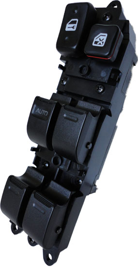
Didn’t want to make a new thread for this… anyone seen this failure before? Jumped this fried bit to get the DS window rolled up

Does the current for the window motor flow through this? Or trip a relay?
3E539B32-435C-46D4-ADEF-3CD33B4224B0.jpeg
3290FEBE-8169-4A10-AA8F-D0433C0B960E.jpeg
 
Saw this tread and had to jump in to see whats going on. I'm on my second personal 80 and as much as I've enjoyed this mod in the past, I've been too lazy to mod this truck. I really do miss it and constantly finding my self pulling up on the switch as it were there.
 
Saw this tread and had to jump in to see whats going on. I'm on my second personal 80 and as much as I've enjoyed this mod in the past, I've been too lazy to mod this truck. I really do miss it and constantly finding my self pulling up on the switch as it were there.
i'm just over here melting stuff :) I've been poking around the EWD, am I correct that the current for the window motor flows through the switch itself? Must be in the case, otherwise the diode current sensing wouldn't work?


So, desoldered the boards hard points to get a better look. This is a big ol resister based on the labelling, that's all I can dig up.
1676739675419.png


New switch coming from switchdoc... hopefully I can just reinstall my diode on the new switch.
 
Yes, you are correct, the power flows into the switch (terminals 7 [up] & 8 [down]), from the relay, and then to the motor (terminals 6 & 13):
1676740230100.png
 
i'm just over here melting stuff :) I've been poking around the EWD, am I correct that the current for the window motor flows through the switch itself? Must be in the case, otherwise the diode current sensing wouldn't work?


So, desoldered the boards hard points to get a better look. This is a big ol resister based on the labelling, that's all I can dig up.
View attachment 3251481

New switch coming from switchdoc... hopefully I can just reinstall my diode on the new switch.
Details on the replacement switch???
 
as far as I can tell the switches just direct the voltage to whatever motor with the corresponding polarity to either move the window up or down. The auto feature engages a circuit that interrupts the path to the motor if an amp draw reaches a trigger point. Not usually a problem going down, but going up with enough bind in the runners and it will stop the window on it's way up on it's own.
 
Details on the replacement switch???
This is the one I ordered, worth a try for $25

as far as I can tell the switches just direct the voltage to whatever motor with the corresponding polarity to either move the window up or down. The auto feature engages a circuit that interrupts the path to the motor if an amp draw reaches a trigger point. Not usually a problem going down, but going up with enough bind in the runners and it will stop the window on it's way up on it's own.
My digging around in the EWD suggests that the current drawn by the motor does indeed go through the switch. For diagnosing purposes, hope this helps anyone looking in the future. I had some real odd behavior with my auto up and down before the component finally fried, like you mentioned it would stop on it's way up and on it's way down as the motor worked harder and the draw spiked. Still need to dig into the root cause, but I suspect it's a regulator or motor issue (and maybe runs?)

Page 108 of the 1996 EWD shows this:
1676740951074.png
 
Lifetime warranty! Even Toyota doesn't supply that, and Expert Assistance to boot! That got a bookmark!

I'm ordering one just to see what the difference(s) between the '96-'97 and '93-'95 switches is/are. I don't remember there being any, but I could be wrong.
 
I just got my switch from switchdoctor, looks like some of the folks who've posted asking about a different switch (big green pcb inside), have one of these aftermarket parts. Here's what mine looks like for reference:
1677192984410.png


Does not appear to be any way to do the auto up mod on these.
 
I just got my switch from switchdoctor, looks like some of the folks who've posted asking about a different switch (big green pcb inside), have one of these aftermarket parts. Here's what mine looks like for reference:
View attachment 3256467

Does not appear to be any way to do the auto up mod on these.
I ran into this problem a while back & couldn’t get no where without their pcb wiring diagram. I ended buying a used oem switch from eBay
Wish you Good luck.
 
i'm just over here melting stuff :) I've been poking around the EWD, am I correct that the current for the window motor flows through the switch itself? Must be in the case, otherwise the diode current sensing wouldn't work?


So, desoldered the boards hard points to get a better look. This is a big ol resister based on the labelling, that's all I can dig up.
View attachment 3251481

New switch coming from switchdoc... hopefully I can just reinstall my diode on the new switch.

I have this exact same problem. Both my LH windows are not working anymore, RH works without a problem. Would it be wise so reconnect the "bridge"? Or is it some kind of safety feature and im a better off with a replacement switch?
 
I have this exact same problem. Both my LH windows are not working anymore, RH works without a problem. Would it be wise so reconnect the "bridge"? Or is it some kind of safety feature and im a better off with a replacement switch?

I could not confirm, but i assume that its a safety feature. Likely something bound causing the motor to pull more current, and this was the first piece to fail. bridging will just push the problem down stream.

I went ahead and replaced my window run, regulator, motor, and switch on that side
 
Last edited:
Hey all, I was hoping someone knows what I'm doing wrong here, since I went through and my window doesn't do the auto up. I don't think I was able to succeed in either step. I cut the tabs, but the switch stops short of hitting its new stopping point - you can see it hovering as if the tabs were still there. with enough force, it maybe moves .5mm further - barely noticeable. is there another adjustment to make? it seems to only move as much as the uncut passenger tab. Also, when I soldered the the diode, the solder seems like it dripped through the holes in the PCB to the other side (see the globes of solder opposite the new diode. I heated up the diode until the solder melted on contact. Is this a bad technique?) rather than pooling on the board surface like the original pictures - does this matter? I've done a fair bit of wiring but never worked with a PCB so I don't know if I needed to prep the surface and didn't.

PXL_20231125_164536520.MP.jpg


PXL_20231125_164629412.MP.jpg


PXL_20231125_164548455.MP.jpg
 
Hey all, I was hoping someone knows what I'm doing wrong here, since I went through and my window doesn't do the auto up. I don't think I was able to succeed in either step. I cut the tabs, but the switch stops short of hitting its new stopping point - you can see it hovering as if the tabs were still there. with enough force, it maybe moves .5mm further - barely noticeable. is there another adjustment to make? it seems to only move as much as the uncut passenger tab. Also, when I soldered the the diode, the solder seems like it dripped through the holes in the PCB to the other side (see the globes of solder opposite the new diode. I heated up the diode until the solder melted on contact. Is this a bad technique?) rather than pooling on the board surface like the original pictures - does this matter? I've done a fair bit of wiring but never worked with a PCB so I don't know if I needed to prep the surface and didn't.

View attachment 3491198

View attachment 3491199

View attachment 3491200
It looks like you didn't get enough heat into the right place. Your solder should "wet" and form a nice fillet around the pieces and flow. Look out your solder joint vs the OEM solder joints. Also, your joint should be shiny, if it's dull it didn't get hot enough and we call it a "cold solder"

Soldering isn't easy, but it does get easier with practice. Plenty of good youtube videos.

The right tip and the right solder go a long way.

Here's a picture someone else posted. Notice they put the diode in from the inside, to get easier access to the pins for soldering.

1700950674977.png
 
It looks like you didn't get enough heat into the right place. Your solder should "wet" and form a nice fillet around the pieces and flow. Look out your solder joint vs the OEM solder joints. Also, your joint should be shiny, if it's dull it didn't get hot enough and we call it a "cold solder"

Soldering isn't easy, but it does get easier with practice. Plenty of good youtube videos.

The right tip and the right solder go a long way.

Here's a picture someone else posted. Notice they put the diode in from the inside, to get easier access to the pins for soldering.
hmm, i ended up with the same situation in reverse even though I heated it long enough that the board started to scorch... in fact, the solder seems to have disappeared, no globes on the backside like last time. the videos I found all have way different boards with bare metal contacts so I can't find a comparison. does this type have special name?
 
hmm, i ended up with the same situation in reverse even though I heated it long enough that the board started to scorch... in fact, the solder seems to have disappeared, no globes on the backside like last time. the videos I found all have way different boards with bare metal contacts so I can't find a comparison. does this type have special name?
Surface mount pcb.

Are you tinning the tip of the soldering iron?
 

Users who are viewing this thread

Back
Top Bottom