81 BJ42 - I have to bring it home and pass inspection (3 Viewers)

This site may earn a commission from merchant affiliate
links, including eBay, Amazon, Skimlinks, and others.

Seems to me you guys are talking about 2 different things here. Trucks with the exhaust manifold on the same side as the steering box (like a LHD with F or H engine fitted, or a RHD with B engine fitted) will have a heat shield fitted to the box, right? Maybe only to the power steering box - not entirely sure.

And there is also a rubber shield fitted to some trucks on the inside of the fender to protect the side of the steering box from debris kicked up in the wheelwell. Only some markets seemed to get those covers and boots, both over the shock towers and over the steering box. Some markets got a rubber pad under between the apron and the fender top, and other markets got a rubber gasket between the lower portion of the fender where it bolts to the cowl.

Hi Chris.

My main computer needs repairs (and I'm too busy to work on it right now although I've finally got the parts I ordered for it) so I have no decent access to the Toyota epc and therefore can't explore this properly.

(I find my copy of the epc works well with WindowsXP but doesn't work properly with the Windows Vista I have on this machine.)

But I can say that I have never seen any evidence of my RHD BJ40 having had a heat shield to protect the steering box from the exhaust (and it really has no need for it because they're not in close enough proximity IMO).

(Note that it did have the usual manifold heat shield higher up that rotted off probably around 1985.)

It did however have a little rubber skirt thingy poked in the front RH-corner of the engine bay (forward of the shock tower and down close to the chassis rail) that I removed very early on in my ownership. As I recall, it was attached very unprofessionally with self-tappers into the RH inner fender so I always assumed it was a the work of the PO.

:beer:
 
Tom,

good to hear from you. I was talking about the cover inside the fender well that goes over the steering box arm. I looked up a BJ40 on the EPC, European spec, and sure enough it is listed, part number 53751‑90300- for LHD or RHD application. Attached also is an EPC scan for the RHD version ,this one from a BJ42. That drawing, on the right below, also shows the seal between lower fender and cowl in the ARL box.
fender apron cover.jpg


fender apron steering box cover.jpg
 
Last edited:
As far as the heat shield goes, I wasn't too sure which models that appeared on, but my impression was that the FJ45 had it in the last couple of years. I have seen that shield before on a steering box, but i can't remember which vehicle or year, or whether it was LHD or RHD
 
Welding today.

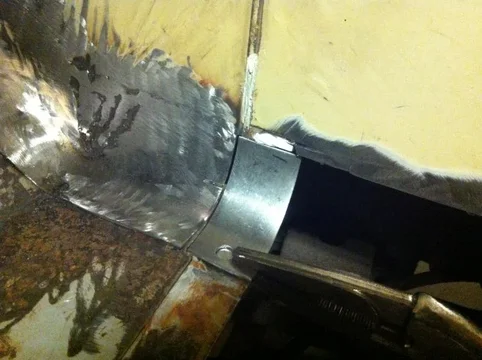
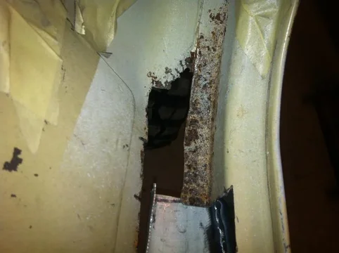
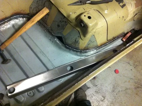
Had to add a little piece to replace an offset section that I cut away. The floor would sit on top and overlap this bit.
IMG_2611.jpg

IMG_2614.jpg

IMG_2615.jpg
IMG_2611.jpg
IMG_2614.jpg
IMG_2615.jpg
 
Again, to use this panel I had to add material and a bend in order to install it as the original was. Here are a few pics of doing that. I clamped the two pieces into the floor as best I could in order to mark and trim the piece I added and have them fit properly after welding them together. I then clamped them to the bench to keep them flat as I welded. Before releasing the clamps I ran across the weld with a hammer to flatten it. The seam will end up inside the rocker and will only be visible from underneath.
IMG_2617.jpg

IMG_2618.jpg

IMG_2620.jpg
IMG_2617.jpg
IMG_2618.jpg
IMG_2620.jpg
 
Back into the floor for a final check
IMG_2621.jpg

IMG_2622.jpg

IMG_2623.jpg
IMG_2621.jpg
IMG_2622.jpg
IMG_2623.jpg
 
More pics for reference
IMG_2625.jpg

IMG_2626.jpg
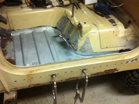
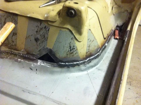
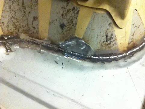
Here you can see the fit of these floor pans. Pretty ugly at first glance but also pretty easy to make work. All I did was... once the floor was confirmed to be in the right position.... start with one tack where the two metals meet. Don't fret, gotta start somewhere. Then tap with a hammer and make them touch somewhere else and tack there too. I jumped around the panel until I had tacks every two or three inches all along the weld line. Then I fine tuned the seam by using a hammer, sometimes with a punch for tight spots, to tighten up the joint. Then I started at one end and did continuous tack welds to the other end. By continuous what I mean is not jumping around. I weld a tack and wait for the metal to cool, like two seconds, and weld another tack right beside and into the previous tack. I did this particular weld that way because it is not a flat area. A flat area would need better heat management to help keep it flat. Because this weld is to a contoured surface, and because it is under the floor mats, I just went continuous. Not a "bead" but tack,tack,tack in a straight line.
IMG_2627.jpg
IMG_2625.jpg
IMG_2626.jpg
IMG_2627.jpg
 
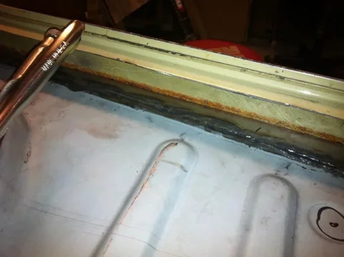
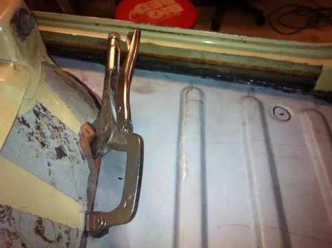
This vise-grip is passing through an area of cut-out rust that is higher than the floor pan will cover but it was a handy spot to clamp
IMG_2628.jpg
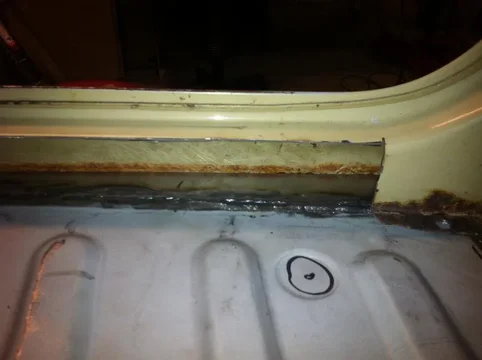
The rear corner will get more metal later. There is some structure underneath that also needs repair.
IMG_2629.jpg
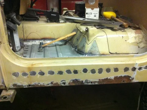
Here is the welded in product. I took the floor back out and punched holes along the front edge to spot weld through as you can see. I also ground off the zinc coating along the weld area because it will contaminate the weld. And the fumes suck too.
IMG_2630.jpg
IMG_2628.jpg
IMG_2629.jpg
IMG_2630.jpg
 
Double checked the floor height matched the rocker before welding the exterior spots
IMG_2631.jpg
The clamp hole
IMG_2632.jpg
the inner rocker needs to be fitted next
IMG_2633.jpg
IMG_2631.jpg
IMG_2632.jpg
IMG_2633.jpg
 
The last pic today. Filled the clamp hole
IMG_2634.jpg
IMG_2634.jpg
 
i have to do my rockers and fab a bit of the floor as well- very timely post! Where was the floor panel from?

I got my inner and outer rockers from pacol and it looks like it will take a little work to get it to all fit perfect. Nothing too difficult- unless I want it to look as good as yours!

Pete
 
The floor pans were from 4wheelauto. They are less than spectacular but they have the ribs in them that I needed most. They would be 100% better if they extended out to the outer rocker and had the spot flange on them. CCOT advertises a better one but I don't know if they have any in stock.
 
\them. CCOT advertises a better one but I don't know if they have any in stock.[/QUOTE]

Almost never do they have panels in stock..although years back I used some Ccot panels and was very pleased...

I used those pans many moons ago, they got the job done..

Rob
 
Agreed.

Here is a long video of installing the inner rocker patch I made. I uploaded straight from the iphone so it is raw unedited footage. Thats prolly better if you are watching for technique. This is the way I do it. There are likely better ways.


image-3109849963.jpg
image-1573936899.jpg
 
Very interesting technique, I would do one inch welds and move them around, sometimes use cold water and cloth also....

I will try your technique on my cruiser...


Rob:beer:
 
Keep in mind this weld is on a corner. Because you have surfaces at 90 degrees to each other they resist pulling and warping. If you notice, I also tacked it in well so it could not move.
 
Here it is cleaned up
image-4159345820.jpg
image-2867716602.jpg
image-1986703195.jpg
 
Switching gears while my air compressor cools.

Friday at work I had this rack cross bar made up in 0.080 5052 Aluminum to test whether I can go aluminum rather than steel.
image-3791496171.jpg
image-623479929.jpg
image-2643241127.jpg
 
It weighs 4.8 Lbs so seven of them in my design would be, um, seven times that. 33.6? Yeah, 33.6. Plus the square tube, so maybe like 60# total. I'll have to check around and see how that compares.

Bolt up the gutter brackets
Walla
203.6lbs dead center according to the bathroom scale today.
image-4151555659.jpg
image-235229007.jpg
image-624405374.jpg
 

Users who are viewing this thread

Back
Top Bottom