
So I spent a lot of time the last few days reading about how to install an aftermarket alarm in the place of the stock one on my truck. I got two remotes when I bought it, but one was mostly smashed, and the second I've been nursing along because the button wasn't responding well. Then over the holidays I found a deal on Amazon for a nice new alarm for $45, and I figured I'd just change them out.
Well, even with all the help on here, it wasn't quite that simple. All the other threads I read either wern't detailed enough, or they were dealing with a slightly different setup than my truck - I guess at some point Toyota changed the wiring harness from what others had writeen about.
After trying to cross reference a number of diagrams, I ended up just creating a brand new pinout and wiring diagrams since I couldn't find any. And this is for anyone else who's lookig to do the same.
First off, if you want to remove the factory alarm, that's pretty easy. Take the lower dash apart, and remove the A/C duct that runs under the steering column. The alarm brain should be stuck to the back of the duct.
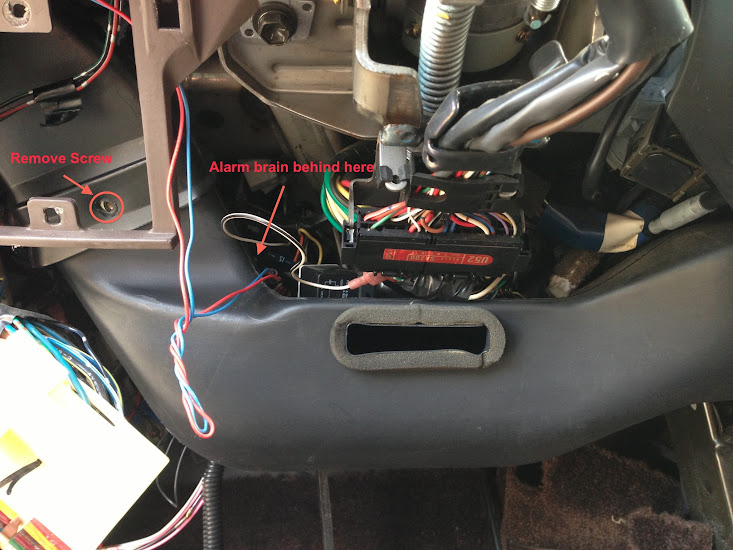
This picture is for reference - you'll need to unplug the connectors and pull the brain. There's also a motion/shock sensor. Mine was at the base of the steering column:

Side note - I didn't know it was adjustable! You can turn the dial to change the sensitivity, or - TURN IT OFF!

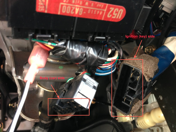
Now, if you want to just remove the alarm, pull all those connectors out, then fish out the other various wires and such. If you pull out all of this, you'll notice a harness that goes between the ignition loom. This harness is also attached to a relay, and wired into the alarm. If you remove this harness, you can plug the key and car side connectors back together - and poof! No more alarm!
If you actually want to *replace* the alarm, that's where things start getting interesting. I'm not going to go into a wire-for-wire installation for an alarm, as each of them are different. What I am going to do is show you where are the wires are that you will need, then you can match them up with the installation manual. You have to know what the different pinouts are, and where to find some other items. The alarm I got had all kinds of bells and whistles to it - even a remote start feature. For all this to work, it has to have the right inputs.
Now, Fireman41 had a great writeup on doing this for a 1996 - but the more I dug into his howto, the worse things got. It wasn't long before I discovered there's an extra pin on the newer models! So if your ignition loom has 11 positions on it, go over here and read Fireman41's thread:
https://forum.ih8mud.com/80-series-...led-diy-remote-start-alarm-keyless-entry.html
If you have a 10-position connector, here's the pinout (this would be "key side")

Pin # Wire Color Function
---------------------------------
1 Green/White
2 Brown IGN2
3 Brown +12V
4 Brown/White IGN2
5 Green/White
6 Black/Yellow IGN/ON
7 Blue/Red ACC
8 n/c
9 Black/Red +12V
10 Black/White Start
If you look at the other side ("car side") of the connector, the wire colors are different.
Pin # Wire Color Function
---------------------------------
1 Green/White
2 Black/Red IGN2
3 White/Red +12V
4 Black/Green IGN2
5 White/Black
6 Black/Yellow IGN/ON
7 Blue/Red ACC
8 n/c
9 Black +12V
10 Black/White Start
These are the basic connections you'll need for any alarm wiring. There are others, but they are all in the kick panel area. Unless you need/want to use the horn - that connection is in the other harness under the steering column.
You will also need connections from the power door locks, the door open circuit, and the parking light switch. Most of these are already tapped by the original alarm, and you can use reuse them. However, I needed the door 'trigger', which was not previously used, and was not listed in any guide I found. Here are the other wires you'll need, and their loctions:
Drivers kick panel:
Blue/black - Lock ("Type B") - requires a diode, should already be in place from the original alarm. On mine, this was connected to a pink wire.
Blue/Yellow AND Blue/Orange - Unlock. BOTH require a diode, and BOTH need to be tied together after the diode. Again, this should already be in place from the original alarm install. Mine was connected to a pink/white wire.
Here's a picture of the connector:

Drivers' side harness, near firewall:
There's a 20-or-so conductor connector up near the firewall. Mine had one tap on it, for the parking lights. That's a green wire, with a white wire used by the alarm. Also in this harness is the "door trigger". In a lot of guides, this is listed as red/yellow. This was NOT correct for me. I finally found out that it is red/green. I hope my time saves someone else theirs!
So here are some other pictures of the installation, just for the heck of it:

Wires, wires.. everywhere...
Then I cleaned it up a bit:

The rest is just finding the right connections and running the wire. Eventually I'm going to also locate the "tach" wire so I can try out the remote start function on the alarm. Otherwise, I turned off the annoying chirping, and I like how it keeps the parking lights on. There's also a ton of outputs on it, so I think I'm going to relay in some other connections for the interior lights. All in all, I'm happy with the installation - hope this helps someone else.
Well, even with all the help on here, it wasn't quite that simple. All the other threads I read either wern't detailed enough, or they were dealing with a slightly different setup than my truck - I guess at some point Toyota changed the wiring harness from what others had writeen about.
After trying to cross reference a number of diagrams, I ended up just creating a brand new pinout and wiring diagrams since I couldn't find any. And this is for anyone else who's lookig to do the same.
First off, if you want to remove the factory alarm, that's pretty easy. Take the lower dash apart, and remove the A/C duct that runs under the steering column. The alarm brain should be stuck to the back of the duct.
This picture is for reference - you'll need to unplug the connectors and pull the brain. There's also a motion/shock sensor. Mine was at the base of the steering column:
Side note - I didn't know it was adjustable! You can turn the dial to change the sensitivity, or - TURN IT OFF!
Now, if you want to just remove the alarm, pull all those connectors out, then fish out the other various wires and such. If you pull out all of this, you'll notice a harness that goes between the ignition loom. This harness is also attached to a relay, and wired into the alarm. If you remove this harness, you can plug the key and car side connectors back together - and poof! No more alarm!
If you actually want to *replace* the alarm, that's where things start getting interesting. I'm not going to go into a wire-for-wire installation for an alarm, as each of them are different. What I am going to do is show you where are the wires are that you will need, then you can match them up with the installation manual. You have to know what the different pinouts are, and where to find some other items. The alarm I got had all kinds of bells and whistles to it - even a remote start feature. For all this to work, it has to have the right inputs.
Now, Fireman41 had a great writeup on doing this for a 1996 - but the more I dug into his howto, the worse things got. It wasn't long before I discovered there's an extra pin on the newer models! So if your ignition loom has 11 positions on it, go over here and read Fireman41's thread:
https://forum.ih8mud.com/80-series-...led-diy-remote-start-alarm-keyless-entry.html
If you have a 10-position connector, here's the pinout (this would be "key side")
Pin # Wire Color Function
---------------------------------
1 Green/White
2 Brown IGN2
3 Brown +12V
4 Brown/White IGN2
5 Green/White
6 Black/Yellow IGN/ON
7 Blue/Red ACC
8 n/c
9 Black/Red +12V
10 Black/White Start
If you look at the other side ("car side") of the connector, the wire colors are different.
Pin # Wire Color Function
---------------------------------
1 Green/White
2 Black/Red IGN2
3 White/Red +12V
4 Black/Green IGN2
5 White/Black
6 Black/Yellow IGN/ON
7 Blue/Red ACC
8 n/c
9 Black +12V
10 Black/White Start
These are the basic connections you'll need for any alarm wiring. There are others, but they are all in the kick panel area. Unless you need/want to use the horn - that connection is in the other harness under the steering column.
You will also need connections from the power door locks, the door open circuit, and the parking light switch. Most of these are already tapped by the original alarm, and you can use reuse them. However, I needed the door 'trigger', which was not previously used, and was not listed in any guide I found. Here are the other wires you'll need, and their loctions:
Drivers kick panel:
Blue/black - Lock ("Type B") - requires a diode, should already be in place from the original alarm. On mine, this was connected to a pink wire.
Blue/Yellow AND Blue/Orange - Unlock. BOTH require a diode, and BOTH need to be tied together after the diode. Again, this should already be in place from the original alarm install. Mine was connected to a pink/white wire.
Here's a picture of the connector:
Drivers' side harness, near firewall:
There's a 20-or-so conductor connector up near the firewall. Mine had one tap on it, for the parking lights. That's a green wire, with a white wire used by the alarm. Also in this harness is the "door trigger". In a lot of guides, this is listed as red/yellow. This was NOT correct for me. I finally found out that it is red/green. I hope my time saves someone else theirs!
So here are some other pictures of the installation, just for the heck of it:
Wires, wires.. everywhere...
Then I cleaned it up a bit:
The rest is just finding the right connections and running the wire. Eventually I'm going to also locate the "tach" wire so I can try out the remote start function on the alarm. Otherwise, I turned off the annoying chirping, and I like how it keeps the parking lights on. There's also a ton of outputs on it, so I think I'm going to relay in some other connections for the interior lights. All in all, I'm happy with the installation - hope this helps someone else.

")