Wiring an 8274 + Albright (2 Viewers)

This site may earn a commission from merchant affiliate
links, including eBay, Amazon, Skimlinks, and others.

lovetoski

SILVER Star
Joined
Jul 12, 2003
Threads
197
Messages
4,644
Hi all,

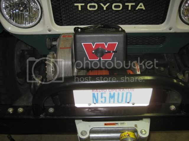
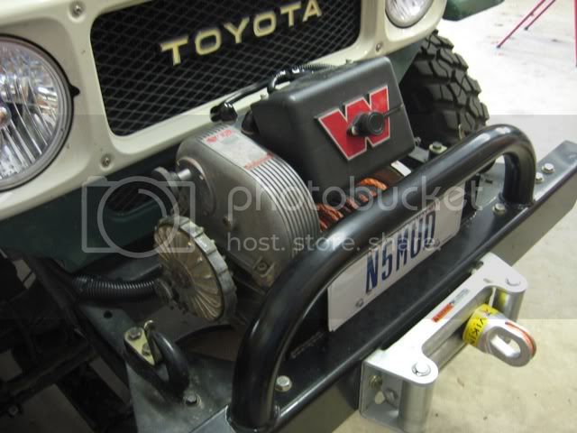
I've been working on installing and wiring my "new" (to me) 8274 into an ARB. I have stalled an albright solenoid in place of the standard 4 solenoids, connected to an in-cab switch (thankyou 12 volt guy). In addition I want to be able to use a Warn wired controller. I don't have a wired controller, otherwise I could do a test to figure this out, so here goes my question...

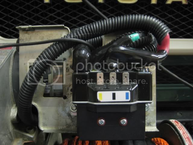
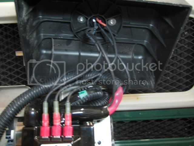
My winch is a three-wire model...the wires to the connector are green, black and white. My question is which is ground, which is "in" and which is "out?"

Thanks in advance for any insight!!
 
The lug closest to the free end of the motor is the armature. The other two lugs side by side are the field windings. The case is the ground. You might have to switch the two field wires to get the in and out directions correct. On th Albright, the battery + connects to the + lug, the armature to the A lug and one of the two field lugs to the F1 and F2 lugs of the contactor.

The way it works is that power flows from the contactor to F1 and out F2 and back to the contactor and then to A and then to ground. To reverse directions, the contactor sends it to F2 first and then out F1 to A.
 
The way it works is that power flows from the contactor to F1 and out F2 and back to the contactor and then to A and then to ground. To reverse directions, the contactor sends it to F2 first and then out F1 to A.

Cool - that makes sense! Thankyou.
 
I emailed warn for specific wiring info on the wired remote and got a quick reply...

"On the older 3 wire system the white was the hot feed to the remote and the green was power-in activation while the black was power-out activation."

I'm going to have to think on this a bit as to how it'll integrate with my albright.
 
A picture is worth a 1000 words.

allbright%20wiring%20diagram.jpg
 
Attached is a useful generic wiring diagram that I found on the interwebs and used to wire mine:
 

Attachments

  • Winch Wiring diagram.pdf
    197.9 KB · Views: 6,835
i believe hustly has a photo in his build thread (70 series section) where there is a photos of the set up.
 
Awesome pics guys - all clear now! I can wire it up this weekend!!
 
The pics + info on here were really helpful - thanks to all.

My goal in this was to have both an in-cab switch (12Volt guy) + the normal Warn wired controller. The albright is mounted onto the stock Warn solenoid backing plate, so with the cover on it looks stock. It all worked out well.

Notes on this pic
2 ga is battery hot.
sheathed 14ga blue+yellow feeds to the in-cab switch.
14ga red is the hot feed for the wired controller, and connects to the white wire.
short 14ga blue connects to green for wired controller (power in)
short 14ga yellow connects to black for wired controller (power out)
Albright Wiring.jpg
Warn.jpg
In-Cab Switch.jpg
 
Sweet! I'm gonna have to keep a bookmark on this thread to when I get around to rebuilding my 8274 & putting on some new solenoids. Thanks! ty :beer:
 
OK, after looking at lovetoski's photos and digging through my parts pile, I figured out that my old-style four-pin /three wire plug and cover would not fit over the Albright, but that my newer-style six-pin / five-wire plug and cover would just barely fit. All the cables and wires just barely fit. I mounted my Albright similar to lovetoski, but as low as it would go and a little to the right of center:

IMG_0776.jpg


This seemed to give me the best fit with the ribs inside the solenoid cover, and the most room above the Albright for routing and attaching cables.

The modern 5-wire controller is very convenient for this application. The red wire is 12v+ and gets connected to the + battery cable stud on the Albright. The black wire is a ground, and connected to the same place as the winch motor ground cable. The brown controller wire is a switched ground, and goes to the center wire terminal on the Albright. On my winch (with a 6hp 9.5XP motor), the green controller wire is the "IN" control, and goes to the right (marked blue) wire terminal on the Albright. The remaining white wire is my "OUT" control and goes to the left wire terminal on the Albright (marked yellow). I believe that for a stock motor, the green and white (in and out) wires would have to be reversed.

IMG_0781.jpg


Like I said, it's a tight fit. I had to move the bottom mounting bolt on the cover about 1/2" to the left so the bolt would clear the Albright. Everything all back together and working perfectly:

IMG_0784.jpg


IMG_0782.jpg


IMG_0785.jpg


Thanks to Pinhead and lovestoski for helping me get the right contactor and figuring out how to do this. :cheers:
 
The modern 5-wire controller is very convenient for this application. The red wire is 12v+ and gets connected to the + battery cable stud on the Albright. The black wire is a ground, and connected to the same place as the winch motor ground cable. The brown controller wire is a switched ground, and goes to the center wire terminal on the Albright. On my winch (with a 6hp 9.5XP motor), the green controller wire is the "IN" control, and goes to the right (marked blue) wire terminal on the Albright. The remaining white wire is my "OUT" control and goes to the left wire terminal on the Albright (marked yellow). I believe that for a stock motor, the green and white (in and out) wires would have to be reversed.

I am going to use the Warn 39886 socket with the Albright solenoid and a Warn M8000. Everything is mounted, as well as the F1, F2, and A cables, I am just waiting on final confirmation on how to wire the socket. Most of the other write-ups show the center, black position on the contactor going straight to ground. Are there any problems using the brown wire, switched ground of the Warn socket? If this is correct, I can finally wire this thing.

01352300.jpg


IMG_0585.jpg


IMG_1077.jpg
 
I am going to use the Warn 39886 socket with the Albright solenoid and a Warn M8000. Everything is mounted, as well as the F1, F2, and A cables, I am just waiting on final confirmation on how to wire the socket. Most of the other write-ups show the center, black position on the contactor going straight to ground. Are there any problems using the brown wire, switched ground of the Warn socket? If this is correct, I can finally wire this thing.

Per my post, that's exactly what I did (brown wire, switched-ground from Warn socket to the middle black blade terminal on the Albright) and it works great.
 
Per my post, that's exactly what I did (brown wire, switched-ground from Warn socket to the middle black blade terminal on the Albright) and it works great.

Yes, your wiring is correct. I'm glad I found this! Thanks.

Mine is finished, including the wireless.

IMG_1098.jpg


IMG_1096.jpg


IMG_1041.jpg
 
extraordinary info here .. question .. where I can source albright solenoid .. ?

Planning to do in my 16.5 and generic wireless remote control ..
 
Digging up an old post to say "thank you" for the suggestions here. I just upgraded my troublesome solenoids on my 8274 as well, although I mounted the unit sideways to make more room for cables and control wiring (and to provide space to put a terminal block).


Users who are viewing this thread

Back
Top Bottom