Navigation
Install the app
How to install the app on iOS
Follow along with the video below to see how to install our site as a web app on your home screen.
Note: This feature may not be available in some browsers.
More options
Style variation
You are using an out of date browser. It may not display this or other websites correctly.
You should upgrade or use an alternative browser.
You should upgrade or use an alternative browser.
Voltage Regulator (ext.) / How it works
- Thread starter bj40green
- Start date
This site may earn a commission from merchant affiliate
links, including eBay, Amazon, Skimlinks, and others.
More options
Who Replied?There is no light but a meter part number 026000-3410?
The voltage regulator has 6wires just the wire harness only has 5
bj40green
Tssss, tssss
- Thread starter
- #165
The voltage regulator has 6wires just the wire harness only has 5
Yes, I noticed that and that's why I asked you.....
What is the part number on the VR 27700-xxxxx?
I'm trying to figure out what you have there. I don't have a picture from your harness connector with that one missing contact.
Rudi
A lot of you don't like electric stuff and especially not complicated things like an external Voltage Regulator. So maybe it's time to explain how this black box with 3 or 6 wires works. It's really pretty simple.
A VR (Voltage Regulator) regulates the charging process of the alternator. Our mechanical VR's have only 3 positions.
Position 1. Full charge
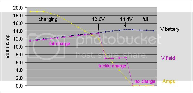
The battery voltage is less than 13.6V.
Position 2. Trickle (or Half) charge.
The Voltage is 13.6V. The battery is now fully charged and needs only to be topped off.
Position 3. No Charge / the battery is full and more charging will damage (cook) the battery.
The Voltage is 14.4V (or between 14.4 and 14.8 depends on the factory setting aka "set point")
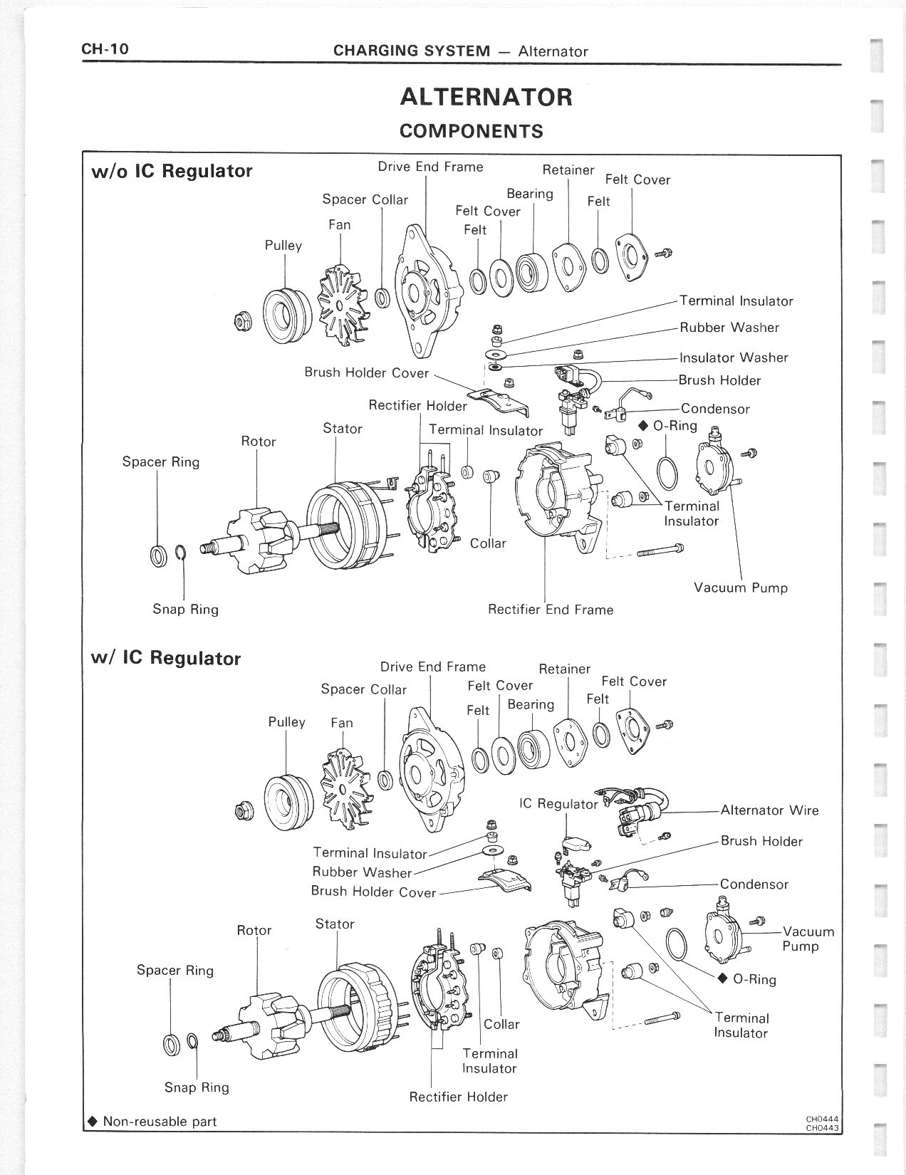
Here is the Toyota explanation from the FSM (Factory Service Manual)
I've "translated" the FSM diagram in this one which is easier to read and understand.
The left part of this diagram is the alternator, the right part shows the Voltage Regulator.
No matter if the VR has 3 or 6 wires, there is always a E, IGN and F wire/terminal.
The other 3 are N, L and B in case of a 6 wire VR. More about this later.
E = Earth / Ground
IGN = Voltage from the Ignition key (= battery voltage) aka "Sense".
This voltage is used to detect how high the battery voltage is.
F = Field. This voltage activates the alternator and controls the output voltage of the alternator.
Look at the VR part of the diagram. The heart of the Regulator is a 3 way switch that is activated by magnetism. Most people call this a relay which is in a way correct.
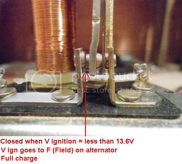
The switch is pulled closed in the top (1st) position by a spring.
The Voltage from the battery (passing the ignition key) goes directly to the F terminal. Therefore the alternator is activated to charge with full power. Note: The resistor is bypassed / overruled / shortened out.
When the voltage goes up, the coil of the switch is energized and builds up a magnetism that starts pulling the switch to the 2nd position.
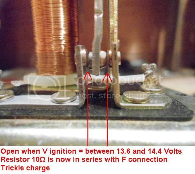
When the battery voltage reaches 13.6V the coil is enough energized to actually pull the switch to the 2nd (open) position.
At this point the switch is open and the 10 Ω (ohm) resistor is now in series with the F terminal. The voltage to the F terminal and thus the alternator, is reduced to approx. 6 to 7V.
The output of the alternator is now decreased and the battery will be Trickled charged.
The battery voltage will continue climbing until the Voltage is 14.4V. At this point the coil is so much energized that it pulls the switch in the 3rd position.
When the switch is in the 3rd position the F terminal is grounded so the charging process is stopped.
Unfortunately (or on purpose by design, I haven't figured that one out yet) now the V ignition is also grounded via the resistor and this creates a lot of warmth and makes the VR feel pretty hot.
Here is the same story but now in a graphic.
Here are 3 pics with the different positions.
Full charge
Trickle or Half charge
No charge / Battery is Full
I also made little movie so you can see it live!
Rudi
HI I'm seeking assistance figuring out how to wire in my current voltage regulator. my truck is a 91 hilux surf and it had a alternator with an internal voltage regulator. now I need to wire in my rebuilt alternator it doesn't have an internal vr .I have an external vr with 6 wire pin my surf has a 3 wire pin and so does the alternator I can cut them all and wire in my own custom connectors but I don't know which color wire does what for anny of the exsiting pins
Coolerman
SILVER Star
- Joined
- Jan 5, 2004
- Threads
- 143
- Messages
- 6,766
- Location
- Paint Lick, KY
- Website
- www.globalsoftware-inc.com
I know you already know this, but the simplest solution for you is to source the correct alternator. Then it's plug and play with no cutting.
Otherwise we will need the schematic for your truck, the schematic or at least a part # for the alternator you are trying to put in your truck and pics/schematic for the 6 pin regulator you have.
Otherwise we will need the schematic for your truck, the schematic or at least a part # for the alternator you are trying to put in your truck and pics/schematic for the 6 pin regulator you have.
I know you already know this, but the simplest solution for you is to source the correct alternator. Then it's plug and play with no cutting.
Otherwise we will need the schematic for your truck, the schematic or at least a part # for the alternator you are trying to put in your truck and pics/schematic for the 6 pin regulator you have.
The schematic is what I'm trying to find. I'm New to the Toyota diesels and I'm doing a build on a hilux surf 2lt. the alternator is in the truck now and has no regulator. I have a 6 pin regulator I can post pics of the alternator and regulator also the 3 wires that went to the old alternator when I get home in a few hrs. I'm also new to the forums here but I plan on a lot in this build and I will have it on here throughout the process. seeking tips/advice or opinions on how to get it to ware I want it .i just rebuilt the engine last winter runs great .love my 2lt and can't wait to daily drive it .the rebuild included bottom end new reinforced pistons new head, valves,camshaft,timeing belt ,waterpump. literally everything but the original block,crank and fuel pump
bj40green
Tssss, tssss
- Thread starter
- #170
It can be done but..... The 6 wire alternator and regulator has a "no charge" check light function. You'll loose this function when you go for the 3 wire alternator set up. The 3 wire set up does not provide the signal for this function.
Now you don't have any control over the charge process. The 3 wire set up comes with an Ammeter (40 series).
The '79 and later 40 series has the 6 wire set up but not the charge check light because they still have the Ammeter.
To know what is happening under the hood you have to install a Voltmeter.
You'll have to find the 2lt engine manual with the electrical schematics to find the connector lay-out, the wire colors and their function.
Once you have that, you can figure out which wires to use and which ones to skip.
Wish you luck,
Rudi
Last edited:
The original alternator was 3 wire connector. the truck has a 3 wire connector. the Regulator is from another toyota diesel just the VR is 6 pin ....also my new alternator has 3 wire pin I will try to find a 2lt engine manual thanks Rudi and coolermanIt can be done but..... The 6 wire alternator and regulator has a "no charge" check light function. You'll loose this function when you go for the 3 wire alternator set up. The 3 wire set up does not provide the signal for this function.
Now you don't have any control over the charge process. The 3 wire set up comes with an Ammeter (40 series).
The '79 and later 40 series has the 6 wire set up but not the charge check light because they still have the Ammeter.
To know what is happening under the hood you have to install a Voltmeter.
You'll have to find the 2lt engine manual with the electrical schematics to find the connector lay-out, the wire colors and their function.
Once you have that, you can figure out which wires to use and which ones to skip.
Wish you luck,
Rudi
Alright thank you will watch for thatThere are 2 different models of 6 wire VR's. One that is not using the N and one that does use the N terminal to function.
In case yours doesn't work..... connect the N (Null) terminal on the VR to +12V
Rudi
hj 60
JT1W0HJ6000960839
Great info, thanks, just found a nice problem in my 1985 HJ60.
search answer:
1-what is burned wire? Thanks Rudi, it is ground (why/how does ground gets burned...)
2-what is type #?
6 wires:
BURNED white/black -- yellow/white -- white
.............white/red -- white/blue -- white/green
.......................CONNECTOR LIP
Thanks bj40green for help and giving a huge slingshot in right direction (while I was )
)

to do:
1-replace burned wire, in progress
2-clean contacts?, in progress
3-test with FSM engine page 305 = CH-21 , replace?

2H engine 338 pag. 2h-engine 338 pag.pdf
Picture of wire: 7 threads in the cable, one thread is 0.3 mm, 4 were left, this might explain why charge was 12.8 with very low amps (17 amps per battery were missing)

Inside looks fine, test FSM pages later:

search answer:
1-what is burned wire? Thanks Rudi, it is ground (why/how does ground gets burned...)
2-what is type #?
6 wires:
BURNED white/black -- yellow/white -- white
.............white/red -- white/blue -- white/green
.......................CONNECTOR LIP
Thanks bj40green for help and giving a huge slingshot in right direction (while I was
 )
)to do:
1-replace burned wire, in progress
2-clean contacts?, in progress
3-test with FSM engine page 305 = CH-21 , replace?


2H engine 338 pag. 2h-engine 338 pag.pdf
Picture of wire: 7 threads in the cable, one thread is 0.3 mm, 4 were left, this might explain why charge was 12.8 with very low amps (17 amps per battery were missing)
Inside looks fine, test FSM pages later:
Last edited:
bj40green
Tssss, tssss
- Thread starter
- #176
B = W to B alternator and Battery
N = W/L (Light Blue) to N alternator
E = W/B Ground
L = Y/W charge light on dash (if present)
IG = B/Y from IGN key in your case W/R (aftermarket VR?)
F = W/G to F alternator

Why are all 6 wires damaged? Where they stuck under a clamp or what?
Rudi
N = W/L (Light Blue) to N alternator
E = W/B Ground
L = Y/W charge light on dash (if present)
IG = B/Y from IGN key in your case W/R (aftermarket VR?)
F = W/G to F alternator
Why are all 6 wires damaged? Where they stuck under a clamp or what?
Rudi
hj 60
JT1W0HJ6000960839
Thanks a lot Rudi 
The wires have a plastic heat shrinked cover from factory.
I will work with this later but we have removed the burned connector contact to solder new wire (searching correct color in old stuff)
We did some continuity tests (not yet with FSM) and as it was charging fine (but low amps) so it might work again with new wire.
Still , when this is fixed, I would like to replace with a new 2017, 24volt unit so maybe search for that and that will be some work finding the right wires.
24 volt voltage regulator | eBay
How this happened is a mystery, what can one (PO) do to mess this up so badly,
Here is the test from FSM, maybe already in the post, I will check later:
Voltage regulator FSm engine CH-21

Voltage regulator FSM engine CH-22

Voltage regulator FSM engine service specifications A-19

charging system alternator FSM engine CH-10

my hj is without IC regulator:


The wires have a plastic heat shrinked cover from factory.
I will work with this later but we have removed the burned connector contact to solder new wire (searching correct color in old stuff)
We did some continuity tests (not yet with FSM) and as it was charging fine (but low amps) so it might work again with new wire.
Still , when this is fixed, I would like to replace with a new 2017, 24volt unit so maybe search for that and that will be some work finding the right wires.
24 volt voltage regulator | eBay
How this happened is a mystery, what can one (PO) do to mess this up so badly,
Here is the test from FSM, maybe already in the post, I will check later:
Voltage regulator FSm engine CH-21
Voltage regulator FSM engine CH-22
Voltage regulator FSM engine service specifications A-19
charging system alternator FSM engine CH-10
my hj is without IC regulator:
Last edited:
hj 60
JT1W0HJ6000960839
First test result: 

charging system alternator FSM engine TEST CH-22
N = W/L (Light Blue) to N alternator
E = W/B Ground

replaced wire and passed all kitchen table test (I think?)
0 ohm = 0.06
200 ohm = 199
0 ohm = 0.07
199 ohm = 196.5
infinity at rest
199 ohm = 198.5
infinity at rest
102 ohm = 99
Now have to connect and test:
Regulator 27-29 Volt (but that was fine before removing)
Relay 8-11.6 volt (the charge light was off so seems fine?)
OEM Colored Electrical Wire
OEM Colored Electrical Wire 13' Roll - Black / White Stripe


charging system alternator FSM engine TEST CH-22
N = W/L (Light Blue) to N alternator
E = W/B Ground
replaced wire and passed all kitchen table test (I think?)
0 ohm = 0.06
200 ohm = 199
0 ohm = 0.07
199 ohm = 196.5
infinity at rest
199 ohm = 198.5
infinity at rest
102 ohm = 99
Now have to connect and test:
Regulator 27-29 Volt (but that was fine before removing)
Relay 8-11.6 volt (the charge light was off so seems fine?)
OEM Colored Electrical Wire
OEM Colored Electrical Wire 13' Roll - Black / White Stripe
Last edited:
Thank you Rudi! Again, that is. What you wrote "W/R (aftermarket VR) did the trick. The rig spent four months in Quito for bodywork and paint, I had no electrical issues whatsoever for the past 2 1/2 years. I think you helped me out back then. Anyway it is a nine hour drive and I made 7 1/2 before stopping to top off the tank and then spent two hours waiting for a tow truck to take me home. Thought the battery would never charge, close to 20 hours @ 6 amps. Maybe less, it was green trickle charge in the morning. So I spent five plus days sorting out the electrics. Knowing that everything worked before I committed the grievous error of replacing VR and Alternator before realizing it isn't the components, it is the wiring. So much fun finding five (windshield washer is fixed yet so make that six) mis-wired features. Plus damage, overspray, etc. really aggravates me. But with your help, I've got it mostly squared away.B = W to B alternator and Battery
N = W/L (Light Blue) to N alternator
E = W/B Ground
L = Y/W charge light on dash (if present)
IG = B/Y from IGN key in your case W/R (aftermarket VR?)
F = W/G to F alternator
View attachment 1393933
Why are all 6 wires damaged? Where they stuck under a clamp or what?
Rudi
Did you ever find a new 24v VR unit that works with your HJ60? Maybe a link to the one you got if you did?I would like to replace with a new 2017, 24volt unit so maybe search for that and that will be some work finding the right wires.
Similar threads
- Replies
- 11
- Views
- 754
Users who are viewing this thread
Total: 1 (members: 0, guests: 1)


