Voltage Regulator (ext.) / How it works (2 Viewers)

This site may earn a commission from merchant affiliate
links, including eBay, Amazon, Skimlinks, and others.

On the bottom side of my VR the light may have washed out the colors but as you look at the picture they are;
Top Left = White Black
Top Right = White Blue
Lwr Left = White Red
Mid-Right = Yellow
Lwr Right = White
Lwr Middle = White Green

Well I re-read my post and now you have me curious about my typo.

Maybe not a typo but the description of the pin locations.

fireworks.gif

Happy New Year!

Rudi
fireworks.gif
 
Voltage Regulator

My bad Rudi, I was referring to the picture of the bottom side of the voltage regulator and where the wires are attached to the regulator. Since I am not sure of the function of each location and where they feed into the wiring harness, such as field, earth, sense, etc. I hesitate to rely on the pin location in the plug.

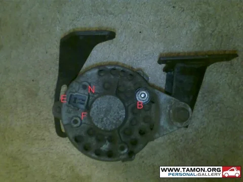
I took this picture of the back side of the alternator and while it shows there are three spades, on the plug only the two side by side are used. I saw a picture on CruiserCorps website of an alternator for my year range and it has a similar plug but I note that it also has a condenser installed. Mine does not have that. It looks like the condenser used on points, is that right? Is that something I should add?

Understanding what/how the various fields of the voltage regulator do would help understanding how to route these from the regulator into the wiring harness. Thanks so much, Lenny.
DSCN1976.jpg
 
Voltage Regulator

This is the alternator I referred to. It has the same three spade arrangement plus the battery connection and also a condenser.
cruisercorpsalt.jpg
 
Hi Lenny,
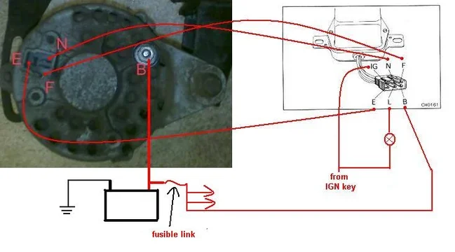
Here is the "how-to-hook-up" picture.
That capacitor (some people say condenser) acts as a noise filter for AM radio reception. For now you can forget about it.
IMAGE_011.jpg
All the wires from the alternator go to the VR.

Rudi
IMAGE_011.jpg
 
So there should be two wires connected to "B"? One that goes to the VR and one that goes to the Battery connection on the starter? That is what my wiring harness instructions show. I have a 175 amp "Mega Fuse" that protects downstream wiring. But what are the other two pins in the plug and where do they feed into the wiring harness as I would only be routing four wires into the plug that connects to the VR?
 
Show me which wiring diagram you're using.
The B from the Alternator goes to the Starter and from there to the Battery.
Or from the Alt to the Battery and from there to the Starter. It doesn't matter but the shortest way is the best way.

F goes from Alt to VR
E goes from Alt to VR
N goes from Alt to VR
IGN from VR needs a switched 12V from the ign key in the "on" position
L is for the "no charge" indicator light. It works in combination with the N connection. You can skip this duo if you don't want this.
B needs to be hooked up to a point that is 12V. That can be the same B terminal on the Alternator or a point close to the battery but after the fusible link.
My choice would be after the fusible link, but any choice is good.
wiring for 6 wire VR.JPG

Rudi
wiring for 6 wire VR.JPG
 
Last edited:
Thank you Rudi. Last night before heading out to celebrate I was reviewing your articles in this forum and determined that the "L" was the idiot light which I will not have and so can ignore. As I said I am using a complete American Autowire Hwy 15 wiring kit and so my instructions of course don't follow Toyota color coding. The wires in the kit are all labeled throughout their length which will help as my approach (as with motorcycles) is clean and accessible. A big part of clean is knowing where all of the wires are going before cutting, splicing, soldering, etc. so I don't end up with a worse situation than I started with, although that would be very difficult to achieve! So I have accessed the Autowire website and posted the links to the various instruction sheets we are discussing. You will see on the alternator instructions how they only address GM alternators and only two versions of them.

http://www.americanautowire.com/PDFLink/92966030 500699 IN 3.0.pdf

http://www.americanautowire.com/PDFLink/92964922 500353 IN 7.0.pdf

http://www.americanautowire.com/PDFLink/92966113 500718 IN 4.0.pdf

http://www.americanautowire.com/PDFLink/92964490 500303 IN 10.0.pdf

http://www.americanautowire.com/PDFLink/92965979 500689 IN 1.0.pdf

http://www.americanautowire.com/PDFLink/92966047 500703 IN 1.0.pdf

Earlier this year you assisted me in trying to figure out problems with the gauges between the 2nd generation (not working, incomplete) and 3rd generation gauge panel that I had purchased. I fried the fuel gauge because of wiring and sending unit issues and so I decided to do a complete re-wire of the vehicle due to various other poor wiring observations. I can tell you that when I removed the wiring harness the only ground was from the battery to the engine block which is of course rubber mounted. The new wiring will use military style battery terminals, five new ground straps and relays to the headlights. I have attached two pictures of the instrument cluster and of the new rear bumper so you get an idea of how I like wiring to be accessible. The license plate light wire is routed down to the plug where I spliced in a bullet for connection. This way the bumper can be removed without much hassle at all, at least with regards to wiring. The way those angled frame channels meet the rear frame channel makes access to the attach nuts quite difficult, as you may well know. Thank so much for your help and wishing you a Happy New Year. I have been retired to Cuenca, Ecuador for almost two years. How long have you been retired to Costa Rica?
DSCN1819.jpg
DSCN1820.jpg
DSCN1949.jpg
DSCN1950.jpg
DSCN1954.jpg
 
Hi Lenny,

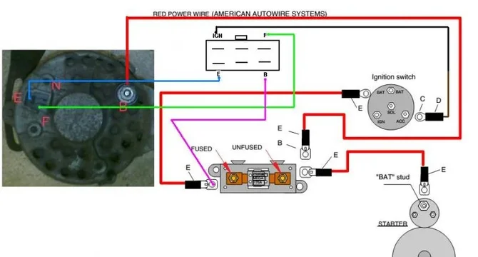
I took the liberty of combining your Alternator and VR into the wiring diagram. This is the result. I just picked bright colors but it's up to you to finish it with the colors you have available.
wiring lenny.jpg

That Cluster is looking sharp. My compliments. Also the wiring on the back looks very professional.

I'm not fully retired yet. I'm 61 so I have a few years to go. We moved from Holland to CR in August 2000. We started a B&B, sold it a few years later and started a Consultancy business for people who want to move to CR. Not a full time job but it gives me enough free time to spend on my Cruiser and here on Mud.
In the meantime the :princess: and I enjoy :steer: and a :beer: now and then.

Rudi
wiring lenny.jpg
 
Starter Solenoid

Thanks Rudi, I turned 64 a few weeks ago. The selection in KPH speedos is very limited and are electronic and I didn't see an adaptor for LC transfer cases. In this model line they offered the 80 MPH speedo vs the 120/160/200 units which on this rig would have the needle barely moving!
In the third Autowire attachment you will see they have a yellow wire that sort of works with the pink wire to the coil. This is the override wire for the ballast resistor. They also show a purple wire that goes to the other side of the starter solenoid, R vs S. Of course the Nippondenso solenoid doesn't have the second terminal. It has the terminal at the bottom that goes to the starter motor, the terminal at the top where the primary battery and alternator wires attach and then a spade terminal where the wire to the positive side of the coil would connect. Currently I have the yellow wire from the spade terminal to the output side of the ballast and if I'm reading the circuit correctly the purple wire would go from the ignition switch to the input side of the ballast resistor and along with the other wiring would have a complete circuit. Is that correct?
DSCN1983.jpg
DSCN1984.jpg
 
Currently I have the yellow wire from the spade terminal to the output side of the ballast and if I'm reading the circuit correctly the purple wire would go from the ignition switch to the input side of the ballast resistor and along with the other wiring would have a complete circuit. Is that correct?

Lenny, I have no idea if that's correct. I'm not familiar with gassers so maybe somebody else with that knowledge can chime in.
Sorry, I can't help you with this problem.
Rudi
 
Thanks Rudi, American Autowire said that to run the yellow I will take it to the starter solenoid with the purple wire, however, I will have to install a 6 amp diode to prevent feedback.

On your VR diagram, did you mean to skip the "N" terminal? Per previous diagram that goes to the upper center pin location in the plug.
 
On your VR diagram, did you mean to skip the "N" terminal? Per previous diagram that goes to the upper center pin location in the plug.

Yep, if you don't use the L (lamp) then you don't need the N (Null) either.
N gives the signal to the VR for yes/no charging. The VR translate that into the lamp on/off.

Rudi
 
Oops. It is in and split loomed into place. If I open the loom up I guess I can remove it. Otherwise the message just doesn't go anywhere, right?

Bags A & B are in place. I need to get some more split loom. Tomorrow I will start the headlight switch bag, "C" and probably "D" turn signals as well. That should be fun considering how many wires Toyota set the turn signal switch up with, six I think. I was looking at the wiring diagram and it looks like four of those wires can be combined into two. Seems like I read something about Toyota running stuff through two flashers for some reason. This fuse panel has a flasher mounted in it along with two relays.
 
Hi Lenny,

Oops. It is in and split loomed into place. If I open the loom up I guess I can remove it. Otherwise the message just doesn't go anywhere, right?

Remove it or leave it where it is. It doesn't go anywhere.

I think that you're now at the point that your re-wiring is no longer relevant to this Voltage Regulator thread.

I think it's handy to start a new thread about this Highway 15 harness so that other people can learn from what you're doing. We can continue from there.

Rudi
 
explanation du cristal


Rudi


ive been googling for a while now to find out how this works, only to find it explained cristal clear here!! it was here all the time :doh:
took the whole ff-in alternator appart, cleaned it, back in the car, no change obviously, its gotta be the regulator or wiring, imma dive on it tomorow!


if you were a girl id kiss ya!
 
This forum is a great resource, and not only for the Cruiser issues but social as well. Rudi directed some world travelers by my place and we had a wonderful visit. Good luck with your dive today.
 
ive been googling for a while now to find out how this works, only to find it explained cristal clear here!! it was here all the time :doh:
took the whole ff-in alternator appart, cleaned it, back in the car, no change obviously, its gotta be the regulator or wiring, imma dive on it tomorow!


if you were a girl id kiss ya!

Let us/me know when you need help.

Save diving!

Rudi
 
Hello,

Thank you for a very good thread explaining how the VR works, and I hope I am not wrong in adding this question to this thread, but it seems like you, Rudi, understand the wiring part and might have an answer to the following question: -if one is replacing an old alternator with a newer one that has a built in regulator how do one go about disconnecting the old VR? In my situation the new alternator is a NPR 24V with a vacuum pump.

Thank you in advance.

This discussion is moved by the OP to a new thread: -? https://forum.ih8mud.com/threads/alternator-for-bj40-1980.819144/

Rudi
 

Users who are viewing this thread

Back
Top Bottom