Builds Splurge Overkill - FJ60 build

This site may earn a commission from merchant affiliate
links, including eBay, Amazon, Skimlinks, and others.

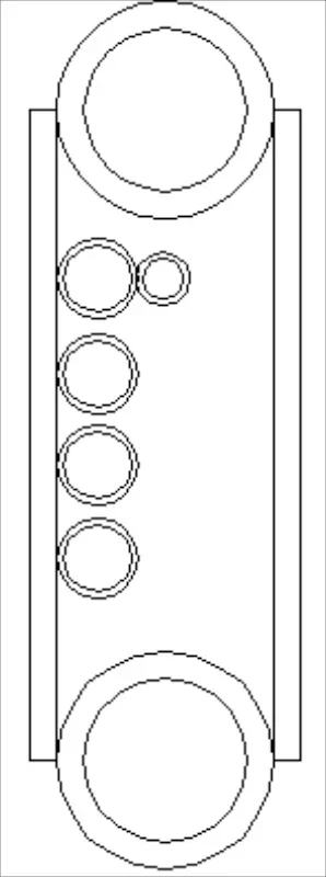
I was going to use a deuce-and-a-half frame and cut it up and box it, but I am having doubts about that. I don't know what kind of steel it is or if it is heat treated. So I am probably going to use some sort of box tube or a built up cross section of tube and plate. I'll sketch up a cross section real quick of that idea. I am really getting anxious to get going on this. Right now it's just incessant scheming...
 
Here is what I was thinking.

frame cross section  033.webp

Use the space in the middle to run conduit for electrical, fuel, air brake lines, etc. Use a nice bend radius to exit, and weld up around the exit to maintain water tightness of the frame.

frame cross section  034.webp

I could even, in theory, use the frame tubes themselves for fluid conveyance. I would like to run hydraulic fluid in them for the steering and fans, that way the frame could act as the reservoir, de-areator, and cooler. But heat into the other components inside the frame is a concern, as well as into the body, which will be right above it. Ideas?
frame cross section  033.webp
frame cross section  034.webp
 
Here are a couple of things off the top of my head:

- Corrosion. If you put conduit through the middle of the frame like you illustrated, then you're creating a lot of crevices where moisture can get in and cause issues. If you run fluid through the conduit, this can produce leaks that will be impossible to trace and fix.
- Fabrication. The only way I can think of producing a frame in this manner is to produce it from scratch, with a tubing bender and flat stock steel. That would be sweet, but it would take a ton of time. Is this your plan?
- Awesomeness. If you built a frame like this, it would make running wires, or fluid, across the length of the truck incredibly easy. I think it's an awesome idea :grinpimp:

Have you thought of using a composite or plastic as the conduit?
 
Good thoughts. I was thinking of using weld-through zinc primer on the inside of the frame before I weld the second plate on the side, and ensuring that all the openings to the frame are welded or sealed. That still leaves the inside of the conduit, though. I suppose I could use stainless tubing... With the right filler I can weld that to regular steel. Would need to research that weld process a bit more. If I run fluids through the center conduits, I would thread a piece of rubber or plastic tubing through the conduit to keep an unbroken fluid path inside the frame. That way leaks should be minimal and if they do occur symptoms would be fluid leaking out the ends of the conduit, and the fix would be pull the tube and snake another through.

I hadn't thought of using composite tubing. I do have a lot of pex left over from other projects... My only concern with that is welding to the outside of the frame plates later to add things on to the truck. Would that melt the conduit inside the frame?

It will be a fabrication nightmare. I am willing to spend time and money on it, though, since it will be the foundation of my truck and I want this to last another 30+ years. I will probably need to make a good cad model, though, instead of just winging it.
 
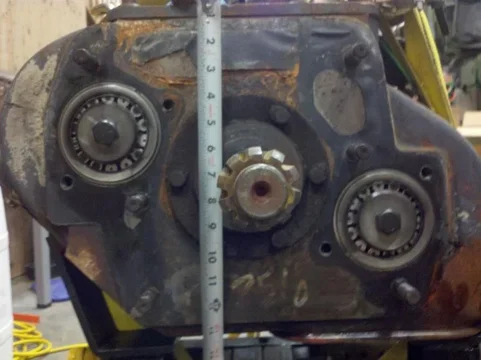
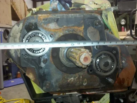
Got the transmission jack parts in yesterday, put it together, and couldn't wait to check fit the beast. Refresher pic:

transmission test fit #1  033.webp

roughly in place, but not centered:

transmission test fit #1  035.webp

About where the shift lever will be, unless I get the forward shift bar housing:

transmission test fit #1  034.webp

Some notes:

-It is about 6"-8" lower than I would like
-I didn't remove the top rear transmission support spring pack, so it can go up at least another inch there.
-It is low in the front, so tipping it back properly will gain another 1/2" - 1" at the front.
-The SAE #1 flywheel housing is still on the transmission. The SAE #2 housing is 2" in diameter smaller. I need to get a clutch kit before I swap them out.

Hopefully in a couple of weeks I can do that, remove the top rear support off of the transmission, and check again. It looks like there is surprisingly little to remove from the tunnel area. Meaning not all of it. ;p
transmission test fit #1  033.webp
transmission test fit #1  034.webp
transmission test fit #1  035.webp
 
You can buy MIG wire that welds mild steel to stainless and TIG rod too. I have a sweet pot rack on the ceiling that has mild steel welded to stainless.

That's an ambitious frame project. I can't wait to see the CAD drawings of your frame. I don't have CAD, but I have a little program called Autodesk I like to play with from time to time. I've been playing with the idea of a tube frame, but I don't know if I want to tackle that just yet...or in the next few years.

That is a massive tranny. I don't envy you making it fit.

That's good info to know. the best part is the welds aren't structural, so they don't have to be perfect.

I am fortunate enough to have AutoCAD and ProE available. I like to do the concept sketches in AutoCAD and the detail work in ProE.

It definately is big. The funny thing was in order to get it under the truck I had to use my gantry crane to pick up the front of the truck. That took less effort on the hand chain of the chainfall than it does to lift the transmission...

Just curious how low does that trans hang under the framerails?
Any pictures of how it sits?

I think I will put the SAE #2 housing on temporarily and remove the upper transmission support tonight and place it in a better position. Then I'll take some pics of that to post up. I think right now it is not too far below the frame rails. The clutch housing is decieving, as it makes the transmission appear tall. It is actually much wider than it is tall in the body of the thing.
 
Why start mocking up the location of the tranny in a frame that you have no intention of using?
 
The mockup is for the transmission tunnel. The transmission is the center of the build. Everything else is based on it. I want the centerline of the transmission as high as possible, and everything else will fall where it may. The frame is custom, so I can design it later to suit my needs.

And I have the transmission, so I can work on this now...
 
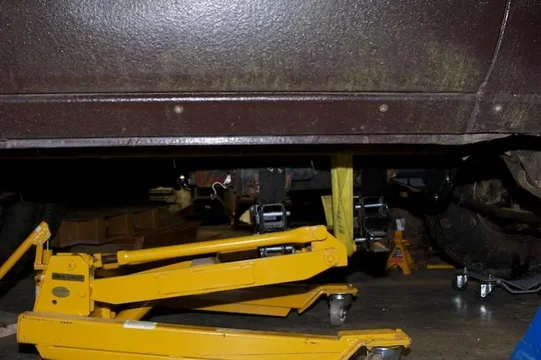
Looking at that transmission underneath the truck, I don't understand how you're going to fit everything in there.
 
Looking at that transmission underneath the truck, I don't understand how you're going to fit everything in there.

Lots of body work! Throw out everything but the body and fab up a new chassis. Custom everything.

No way this would fit within the constrains of the original design.
 
This is the main interference point.

transmission test fit #2  040.webp

From underneath:

transmission test fit #2  038.webp

That is one of the countershafts. The passenger side one is high, and the driver low. You can really see that in the previous post with the clutch housing off. That works well, since less modification to the driver footwell is required. I really didn't want to sit sidesaddle... There is still the slave valve on the driver's side, but it is farther back on the transmission.
transmission test fit #2  040.webp
transmission test fit #2  038.webp
 
There are two bosses cast on the underside of the transmission. They can be drilled and tapped for a rear mount, eliminating the space-eating upper one that came with it.

transmission lower rear mounting boss detail  041.webp
 
What's that tranny? In layman's terms, not the number. What's it out of? What are it's capacitys? It looks like it is out of a tank. Or a Kennworth.

I like the progress.
 
What's that tranny? In layman's terms, not the number. What's it out of? What are it's capacitys? It looks like it is out of a tank. Or a Kennworth.

I like the progress.

Thanks!

The transmission is an Eaton Fuller. It is part of Eaton's truck drivetrain component line they call Roadranger. That includes axles, clutches, etc. These transmissions come in a wide range of styles. Hundreds. Mine is a RTO-14709mll. To break that down: rto stands for Roadranger Twin countershaft Overdrive. The 14 is the nominal torque input rating, in hundreds of foot-pounds (actually 1450 for this model). The 7 is the design level (6 had straight cut auxiliary gears [loud!], 7 had helical cut ones, and 9 has an improved rear output seal design.) The last two digits are the number of forward road gears. 9 in my case. The next letter is the ratio identifier (in my case, the M is a lower deep reduction reverse gear than the A gearset that was also available). The last two letters indicate that there are two deep reduction gears below the 9 road ratios, meaning this transmission is actually an 11 speed. The two deep reduction gears are not meant for progressive shifting, only for speed control. Whew!
This particular transmission was used extensively in cement mixers and dump trucks, so they could go slow enough to keep pace with paving machines and not burn clutches. Usually those trucks have GVW's around 60,000 pounds. Often they had the Cummins ISC (8.3L) or ISL (8.9L) as a powerplant, too... It is not a very common model, so I looked for a while to find one that I could get for a good deal. They are spendy otherwise.
The RTO line of transmissions are known for being extremely tough, long lasting, and easy to shift (even though there are no synchronizers in the front half of the transmission). It's not unheard of for these to go 500,000-750,000 miles between overhauls, and millions before they are scrapped. And those are hard miles. Mine has 130,000 on it and internally looks new from what I can see.
I will post a link to all of Eaton's literature on the beast as soon as I get to a computer since the app on my phone is not cooperating. The service manual is an excellent read, I think. Lots of pictures, and has all the power flow diagrams for each gear ratio to help visualize how it works.
 
Those Eaton transmissions are nice, I was thinking about putting an 8LL in my truck for a while. I even have one sitting around but 700# for a trans was a bit much for me.

Keep up the work, this thing is gonna be cool when it is finished.
 

Users who are viewing this thread

Back
Top Bottom