Builds Splurge Overkill - FJ60 build

This site may earn a commission from merchant affiliate
links, including eBay, Amazon, Skimlinks, and others.

That's good to hear, stevo. I think this engine is going to stick out the hood anyway. I am planning on 28 inches from crank centerline to valve cover, based on a drawing I found for a firepump application. That was 24 inches, but it didn't have the jake brake.

I might have to remake the bottom of the oil pan sump out of 3/8 plate since it hangs so low. Right around 15 inches from the crank centerline.

I really should wait until I get the engine, but I hate waiting.

Yeah waiting sucks, but it does save a lot of time reworking things.
If you are going to make a custom oil pan, I hate to say this, but I would wait until you get the front axle in to make sure you have plenty of clearance around the diff.
It sounds like the motor is gonna be fun to fit into the engine bay heightwise. side to side there is a lot of room. I know I have tons of space on the sides of my motor.
 
Good points. I will leave it alone for now.

The pan will probably need to be worked to fit around the front diff like you suggest. I am trying to keep it low!

I am seriously debating painting the top of the valve cover a real nice cummins red auto body paint and just cutting the hood and letting it stick up. It's either that, or a cowl. The motor home versions have the oil fill in the front of the pump drive gear, same as the 12v 5.9, since you can't reach the other one. So I can weld up the one on the top of the valve cover and tamper-proof it.
 
I thought you were going to fab a new frame? I would start there. Everything is going to have to revolve around the frame. Once you've built the frame, mount the tranny, engine, etc... then, lower the body on and carve it up according to fit.

A Max Ellery manual has great drawings of frames that would be right up your alley. I'm not saying you would copy it because you're building a stouter frame, but it gives you mounting point specifications. Then you can fabricate the frame with your engine, tranny, etc, and your mounting points in mind. This should be easy for you with CAD.

This is kind of like a full sheetmetal buggy build. I will start with the drive train, then wrap the frame around it. the transmission is the center of the whole project and can only go in a limited place. Too far back and I'll have to sit sidesaddle to clear the bellhousing, and too far forward and the front will be needlessly long. I am getting that happy spot figured out now, then I can figure out how much I have to stretch the front and rear th fit it all. Also, I do not intend to mess with the firewall or stretch the body in between thr a and b pillars. This is definately a different way of doing business. Ultimately the frame size and shape is going to be dictated by the best fit geometry around all the stuff and a good stress analysis.

I've never heard of an Ellory manual. They look nice. I did keep the fsm for my truck, so I have all the body mount dimensions.
 
One possible way to mate a t-case to a fuller.

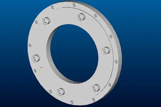
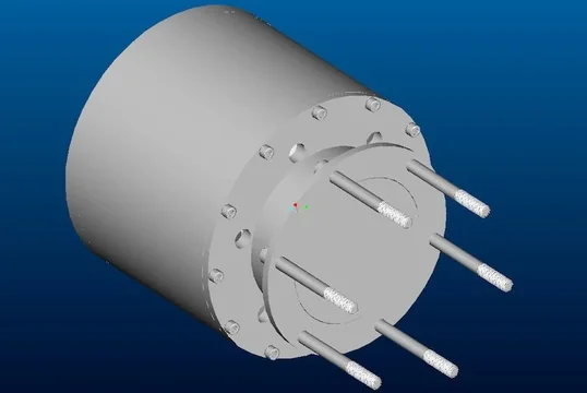
Got a chance to do some design work today. My thinking behind this design is to be able to unbolt the t-case and part of the adapter in case I break the t-case. I will carry a full size spare rear driveshaft so I can bolt it in and drive home. Or if I want to tow a 53' container over the rockies... :D

The part that bolts to the NW Fabworks or ORD reduction box:

adapter  074.webp
adapter  075.webp
adapter  074.webp
adapter  075.webp
 
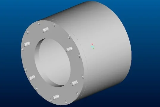
Attaching to that is the ring that goes around the yoke. This would actually be bolted on before this assembly gets bolted to the t-case. Alternatively, I could weld the two together and get rid of a bolted joint for ease of fabrication.

adapter  076.webp
adapter  077.webp
adapter  076.webp
adapter  077.webp
 
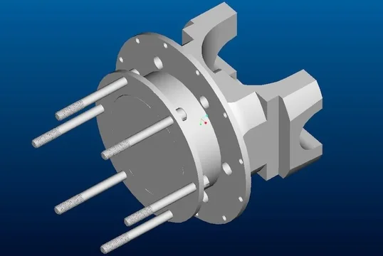
This is the part that bolts onto the transmission output bearing retainer. The yoke needs to be removed to put this on. The long bolts replace those holding the retainer on the transmission. To picture where this is, look at any of the preceding pictures of the aft end of the transmission. the bearing retainer is the 3.5" long tube of steel right behind the yoke. It is held on by 6-3/8" bolts.

adapter  066.webp
adapter  067.webp
adapter  066.webp
adapter  067.webp
 
With the cross bar in the yoke. The back of the bar is bored to center on the transmission output shaft, and the center bore would be splined to whatever I desire. Most likely 32 spline. I'd use a short 4" chunk of splined shaft to go between this and the female splines of the t-case.

adapter  070.webp
adapter  071.webp
adapter  070.webp
adapter  071.webp
 
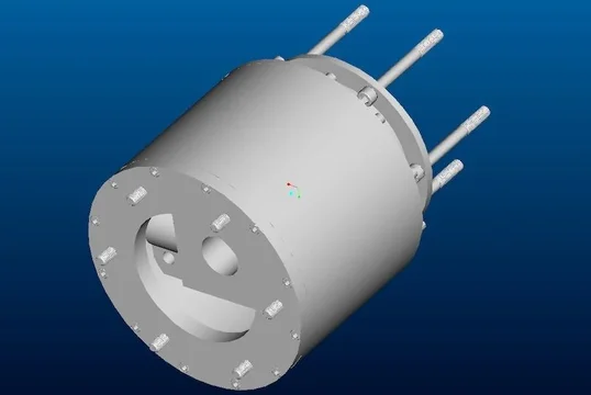
The final assembly. All told, it is ~8.5 inches from the bearing retainer face behind the yoke to the mounting face of the t-case. Access hole for the base mounting bolts would be plugged after assembly to prevent the whole thing from filling with chit.

adapter  072.webp
adapter  073.webp
adapter  072.webp
adapter  073.webp
 
glad to see your putting that tub to good use kevin! what are you plannin on towin with that plantery rear end!? anything if you want. cant wait to see it when your done.
 
glad to see your putting that tub to good use kevin! what are you plannin on towin with that plantery rear end!? anything if you want. cant wait to see it when your done.

It is going to be very valuable to me. In fact, I dropped the duct portion that has the AC core in it when I was undoing my dash and broke a tab off of it. I now have a replacement! I have no idea what I am going to tow with this. Possibly a big 5th wheel, then I can get rid of the 5-ton and have less maintenance cost and more functionality.
 
Do you think 6-3/8 bolts is going to be enough? You are dealing with mass amounts of torque .

There are only 6 - 3/8" bolts holding a NP205 if it is the round pattern... But you are correct. There is a lot of torque available. I am going to make a crossmember that will support the rear of the transmission, and the t-case will be tied in to it as well. This adapter shouldn't take any force at all, which is why I am not stressing over the materials I am making it out of.
 
There are only 6 - 3/8" bolts holding a NP205 if it is the round pattern... But you are correct. There is a lot of torque available. I am going to make a crossmember that will support the rear of the transmission, and the t-case will be tied in to it as well. This adapter shouldn't take any force at all, which is why I am not stressing over the materials I am making it out of.
That would work . So a external brace in essence? Take the sear force away from the bolts? I might have to drive across the hill to see this monster when its finished!
 

Users who are viewing this thread

Back
Top Bottom