Slee LX Slider Notes (3 Viewers)

This site may earn a commission from merchant affiliate
links, including eBay, Amazon, Skimlinks, and others.

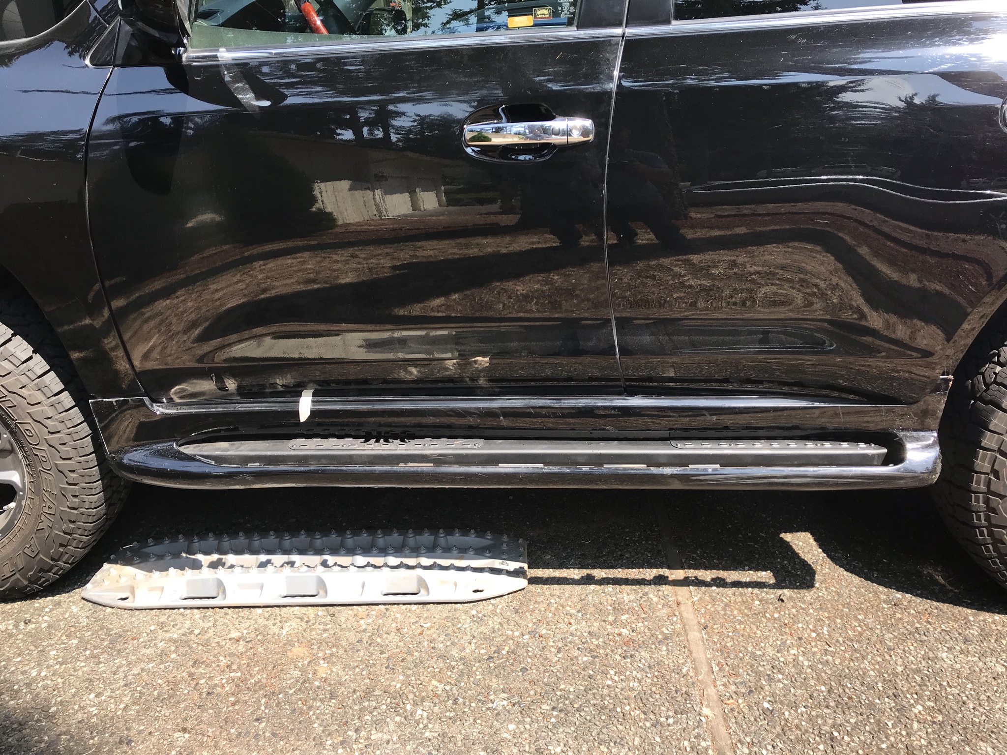
I took my steps off to install the sliders, then temporarily re-installed over sliders to make the cut:


ztzRh1C.jpg
 
It's pretty straightforward as to where to cut at the inflection point of the curve. Having them on the car on AHC high puts them in a good stable position to cut. You'll want to finish the cut edge with any sanding or cleanup prior to mounting the slee step, or you'll prob have to remove them to do so at that point.

1612480058426.png
 
I’ve read as much as I can and have gone over the SLEE instructions a hundred times. Maybe this will become obvious when I actually put the sliders to the body but I can’t figure out one thing.

On the LX do you actually drill a new hole or just enlarge an existing one for the rivnut? The SLEE instructions say nothing of drilling a new hole but I’ve seen at least one mention in another thread that it must be done.
If I remember correctly, you have to enlarge an existing hole for the rivnut.
 
If I remember correctly, you have to enlarge an existing hole for the rivnut.
That's correct. You need some random sized bit like 19/32. Some people go smaller and waller it out some.
 
I just installed mine this weekend. You are enlarging one hole on drivers side.(LH side).

You can also do the step where the slider is hung first to figure out where the hole is and easily drill out the hole with the slider in place. The hole is for one of the brackets that is not attached until you drill the hole, so nothing is in the way. I used @TeCKis300 method of drilling out with a step bit to 1/2", then i used a Dremel with grinding bits (took me 5-6 crappy walmart bits) to enlarge the hole until the rivnut fit. By fit, i mean, i was able to get the curved end of the rivnut into the hole by hand, then a light tap with hammer set it in the rest of the way. I didn't attempt the hammer until i could get all of the rounded edge into the hole.

Quick notes since it made a huge difference in install time for not knowing which tools vs knowing. (6 hours for first slider, 2 hours for second). I bet i could do a full set in under 4 hours now from soup to nuts.

This may be repetitive, but here is my cliff notes on the install now that I've done it once.


Useful tools:
A ratcheting 9/16 wrench for tightening the bracket bolts that you don't have clearance behind for a socket and driver (probably not necessary if you aren't doing the light kit as those brackets are what is mostly in the way).
A ratcheting 12mm wrench for the rear bracket bolt. The acute angle of the bend in the bracket doesn't allow clearance for much behind that bolt head.
Wobble joint and a couple extensions to get at the bolts on the vertical side of the frame.
Ratchet straps in case you need to pull on any of the brackets to get holes to line up. I ran the ratchet strap through my wheel, then wrapped it around the bracket and tightened until they were in the right spot.
2 Jacks for holding things in place and final placement of slidersteps.

Steps:

Step 1a. Pre assemble the sliders as the instructions say with the outside brackets, step plates, and lights if you have them. Make sure you get the end brackets on each slider in the correct orientation. The directions have been corrected since some earlier mudders reported to SLEE that it was difficult to orientate. If you have the lights, it is cleanest to connect them to the connector at the b pillar, so keep that in mind with pre wiring, i had way too much wire, since i thought i was going to connect at the rear. In hindsight the way i wish i had done this was to unplug the b pillar connector and cut off about 8-10" of that wire (towards the step) and connector then take that to my bench and wire the two lights to the connector and wire tail. This would give you the least possible butt joints and excess wire. On my truck the 2 red wires on the truck harnesses were the +12v on either side. The (-) was different colors on either side.


1. Put truck in HI setting (or lift however you choose). Disconnect wiring harness between truck and LX Steps, the connector that is under the B pillar, not the one at the rear of the step.
2. Remove the 6 bolts holding the 3 lower step brackets to the body.
3. Cut the painted sections of your side steps on both sides below the line you will ultimately want. A oscillating multi saw breezes through this. I had one with the semi-circle blade and one with the strait blade. I mostly used the semi-circle blade if you only have one option. May want to remove your front mudflaps if you still have them before this step. Mine were trashed after i removed them for larger tires.
3. Remove the lower half of the step along with the black plastic step. As long as you disconnected the one wire at the B pillar, this will just drop out with a slight bit of force.
4. Remove the bolts holding the AHC bar brackets to the frame. I didn't bother taking any bolts from the brackets to the AHC bars. Just the 7 bolts that connect to the frame. Wobble extension helps here, and its much easier to do with the side steps already cut out. I used jacks to catch the ends since i was doing it myself.
5. Finish your cuts on the side steps. Use a little sandpaper to clean up the cuts. I played with a few options on this, but nothing really looked good trying to leave any extra material, so i ended up in about the same place as @TeCKis300 cut his. I don't really like that much either, but i don't think anything looks "great" other than getting the LC rocker covers.
6. Set the assembled step next to the truck to see which 2 sets of holes (from the removed ahc bar brackets) are used to attach the welded slider step brackets. Use the M8 bolts and big washers (plus little washer to retain the big washer) and partially thread into the top holes of the frame for where the two slotted bolt locations on the brackets. Then hang the sliders from those two bolts.
7. On drivers side, now you can identify which hole your bracket needs to have drilled out. Drill out the hole, make sure the rivnut fits (don't install). Remove rivnut and paint the exposed metal. While waiting for it to dry go work on other side. Rivnut install: I used a longish( 3" maybe) M8 bolt and one standard nut and 2 of the big flat washers provided for slider install as my rivnut tool. Thread nut and then slide two washers onto M8 bolt. Thread M8 bolt to rivnut (use all the rivnut threads). Tap rivnut into hole. Stabilize end of the bolt and turn the nut until you can't turn it anymore. If your wrench is on the smaller side (like mine was), i recommend using a larger adjustable or something for more leverage.
8. I don't think the order matters much at this point. I started placing all the bolts that connect brackets to frame. I did not tighten any bolts until I had them all in. I had to use the ratchet strap trick 3 times for different brackets. I suspect this is just lottery on how well things fit together depending on what you try to install first. and so on. Obviously the things that are the easiest to "move" are the two end brackets, so if you need to stress something to get it to fit, those are the best to work on.
9. Once all bolts are fitted and loose, i used my two jacks to jack up the slider to the clearance from the body i wanted. (May find it necessary to use the jack to line up holes as well)
10. I started tightening all the bolts. Remember if you are using the split washers you don't want to over tighten or you will completely flatten them and they won't be doing there job of preventing the bolts from backing out.
11. Ziptied the wiring for the lights after testing them.
 
Last edited:
The lights shoot out sideways and not down?
 
sideways.. but you still get a lot of light.
interesting! It could be the camera angle, but do they hang down below the slider mounts? As in, they may get knocked off on a scrape?

Photos are of my installation

Any reason you have lock washers on the bolt side?

1648265001499.png
 
interesting! It could be the camera angle, but do they hang down below the slider mounts? As in, they may get knocked off on a scrape?


Any reason you have lock washers on the bolt side?

View attachment 2962741
I think it may be the angle. They mount from top of slider, so don’t end up below. No comment on his lock washer placement.
 
interesting! It could be the camera angle, but do they hang down below the slider mounts? As in, they may get knocked off on a scrape?


Any reason you have lock washers on the bolt side?

View attachment 2962741

Nah they are all tucked inside the step.
 
No idea. Ask SLEE. They did the installation.
Interesting!
I always thought the lock washer went on the nut side. Maybe slee knows something I don’t. Or maybe the intern put your sliders on 😂😬🤷🏻‍♂️
 
Someone set me straight:
I was test fitting all the things when I noticed one of the bolts wouldn’t thread into the captive nut on one of the arms.
At first I thought, “no big deal, maybe some power coat stuck in there.” But it was a much bigger chunk of metal. I send these pics to Slee, and they respond back with “tap the nut.”

And then I responded back with, “Please verify the thread size to tap with or send me one.”

And then get this message:

There are ultimately four ways to handle these imperfections;
  • Use a pick tool and try to remove
  • Use the bolt and thread in by hand with a rachet and use the bolt as a thread chase
  • Use a Thread chase
  • Use a Tap

It’s definitely not PC, the bolt won’t budge it, and a pick didn’t work. Maybe the nut was damaged when they welded it on?

I’m a little annoyed. These things weren’t cheap, and now i have to deal with fixing this before I can install. I don’t have the size, so I have to order and wait until it arrives. Plus, all time I wasted e-mailing and complaining on here 🥴

Would you be annoyed as well or just deal with it and move on?

8FB91579-EB2D-44C8-A8AA-763F7BCBD01B.jpeg


11B21E1A-36BC-4794-94B3-7BECA53C0700.jpeg
 
Someone set me straight:
I was test fitting all the things when I noticed one of the bolts wouldn’t thread into the captive nut on one of the arms.
At first I thought, “no big deal, maybe some power coat stuck in there.” But it was a much bigger chunk of metal. I send these pics to Slee, and they respond back with “tap the nut.”

And then I responded back with, “Please verify the thread size to tap with or send me one.”

And then get this message:

There are ultimately four ways to handle these imperfections;
  • Use a pick tool and try to remove
  • Use the bolt and thread in by hand with a rachet and use the bolt as a thread chase
  • Use a Thread chase
  • Use a Tap

It’s definitely not PC, the bolt won’t budge it, and a pick didn’t work. Maybe the nut was damaged when they welded it on?

I’m a little annoyed. These things weren’t cheap, and now i have to deal with fixing this before I can install. I don’t have the size, so I have to order and wait until it arrives. Plus, all time I wasted e-mailing and complaining on here 🥴

Would you be annoyed as well or just deal with it and move on?

View attachment 2972134

View attachment 2972156
Must have been the intern responding to your question. LOL!
 

Users who are viewing this thread

Back
Top Bottom