improving flow for the 3FE’s top end (17 Viewers)

This site may earn a commission from merchant affiliate
links, including eBay, Amazon, Skimlinks, and others.

Jim - What's your DD? And do you think the Extrude Hone did the job?
A little German car.:meh:
It made more power at lower boost after the extrude hone (improved pumping efficiency). :cool:
 
Finally getting around to some comprehensive flowbench testing this afternoon. I'm a third through it now, and should have some numbers and thoughts to post in a few hours. With the set-up I have, seems I can only test down to about 0.15" of valve lift, less than that and the vacuum collapses the "expansion cone" thing-a-ma-bob and the water level in the manometer gets close to the end of my scale.
 
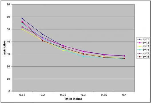
Okay, so I've gone through and gathered some "vacuum" readings off of the flow bench. This round is from the unaltered head, with no intake bits attached. As you can see from the photos, I rimmed the port with some plasticine to kill the impact of the 90* corner. Values were gathered from 0.15" (0.10" for one good cylinder) to 0.40". On the poorer flowing cylinders, the vacuum created at 0.10" lift would collapse the cone on the flowbench set-up. There is a fair spread of measured restriction, and it seems that odd numbered cylinders get the better stock flow. :hmm:

IMG_4515small.jpg


The probe is made from thin brass tubing, and is hooked to a separate manometer. It is used to pick out where exactly the flow is concentrated in the port. I need to play around with it some more, but it seems clear at this point that for ports that lead straight in from the manifold (cyls 2 & 5) the flow is pretty evenly spread in the port, while for ports the "swing" into the bowl (1 & 6) the flow is concentrated on the inside of the arc. It's also apparent that the majority of the flow hugs the port floor and short radius in the bowl area, and dumps through the near side of the valve (at the flow the vacuum cleaner can generate at least). This suggests the valve guide/boss/stem significantly impede flow, and attention paid here (undercut stems on the new valves, removing metal from the boss area, narrowing the cross-section of the guide) should pay dividends.


IMG_4517small.jpg


IMG_4518small.jpg


Values given are height to which the water is pulled up the inclined manometer (i.e. vacuum) but I'm not going to bother converting to inches of water or anything, given that there is no way key it to flow units with this booty fab unit. The set-up is zeroed in with a "standard" orifice plate after every 2 readings to make sure that the readings are suitable for comparison between cylinders, and of before and after results. The values can be thought of as "restriction", the greater the restriction, the greater the vacuum value read off of the flow bench. I figure the measurement error in the readings is around 0.5 (cm) when the value is around 35 (cm), and greater when the value is greater. There is likely a bit of error in the lift for each reading as well, since this isn't a precise set-up (lift set with a set of vernier calipers, and held with the vice-grips and rubber tube). I think the variation seen between cylinders greatly overshadows any error, however.
flowbenchchart.jpg
flowbench.jpg
 
Last edited:
Out of curiosity, does anyone know if thermal coatings (for the chamber, valve heads, piston tops) have come down in price to where they are reasonable to do on street engine? Or are they still pretty much reserved for competition builds?

Jim, do the Si valves come with any coating? The description on the website seems to suggest it (Black Knight coating), but does say anything specific about it. I'm getting SEV-2809 and SEV-3091.
 
Last edited:
Jim, do the Si valves come with any coating? The description on the website seems to suggest it (Black Knight coating), but does say anything specific about it. I'm getting SEV-2809 and SEV-3091.
I use the cheapest stainless claimer valves. They are not coated, AFAIK.
 
Well, I started some grinding this evening. Went pretty smooth actually. I've got the seat transition area of #6 pretty much done. Started with the die grinder and carbide bits, then switched to a grinding stone on the end of the Dremel flex shaft, and eventually sandpaper. The die grinder is great for removing metal quick, but lacks the control and nice finish you get with the grinding stone. Sand paper was pretty much just used to smooth the short radius where you can't get in with a rotary tool. I think I spent about an hour at it, but the rest should go in about half that time.

I also figured out why 1, 3 and 5 flow better than 2, 4 and 6. I forgot to plug the spark plug holes on them :doh: 2, 4 and 6 were still plugged from when I poured the silicone. So, when I have a chance, I'll re-do the stock flowbench testing on the odds, and see what's been gained on #6 so far. Then back the the grinding the next warm day we get. Once the seat transitions are all done and tested, I'll move on to the valve guide/boss area and see what can be done to try and get more flow over to the far side of the valve.

A little engine porn:

#5 untouched
IMG_4560small.jpg

IMG_4561small.jpg


#6 smoothed out
IMG_4551small.jpg

IMG_4558small.jpg


And comparison between them
IMG_4564small.jpg

IMG_4565small.jpg

IMG_4566small.jpg

IMG_4567small.jpg


Well, off to bed, I need to head out for a snow run in 6 hours. :bounce2::steer::bounce:
 
Fantastic work, it takes so much more time to catalouge your progress for others to see, and i know we all really appreciate it.
 
Fantastic work, it takes so much more time to catalouge your progress for others to see, and i know we all really appreciate it.

Thanks :cheers: Good to know there are some keeping an eye on this. I kind of like scrolling through all the photos too :) kinda helps keep me motivated.
 
Took some time to work on the head again today. Got the intake valve bowls for 4 and 5 up to the same point as shown for 6 above. They look and feel great.

Ran flow tests. 4 and 6 (which were the worst at low lift before) have come in line with the rest of the cylinders (cylinder 2 is the only one decent for comparison, as 1, 3 and 5 didn't have the spark plug holes blocked off in the original tests, and thus gave junk data).

First the data from the stock head, then the data after 4, 5 and 6 have been bumped.
flowbench.jpg
flowbench2chart.jpg

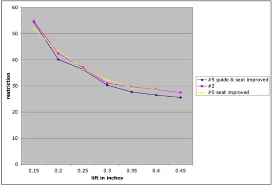
While bringing the cylinders into better balance is nice, there wasn't the wholesale improvement of flow I was expecting. Hopefully once I put some effort in the valve guide area I'll have more significant improvements to show. It's still clear that the vast majority of flow is dumping down the short side of the valve.....
flowbench.jpg
flowbench2chart.jpg
 
Played around some more this afternoon and got one of the cylinders all spruced up around the valve guide. It's a bit difficult to get in with the grinding tools, and especially with your fingers to smooth it out with some sandpaper. It might be a bit difficult to get an idea of the depth to which the port has been cut, you should be able to get an idea of what has been done in these photos. Still needs some more attention with the sand paper, but I'm anxious to test it out.

First #2 (the one that is being left untouched so it can be used as a standard for comparison) then #5 in altered form.
IMG_4623small.jpg

IMG_4624small.jpg

IMG_4625small.jpg

IMG_4626small.jpg

IMG_4627small.jpg


Should get the flowbench fired up in a bit to see what improvements have been made. :cheers:
 
A comparison of the restriction measured for #2 (unmodified) and #5 (after the seat/bowl area was improved, and with the addition of attention to the guide area). As was mentioned above, working on the seat/bowl area seems to have narrowed the spread between the cylinders. As can be seen here, attention to the guide area has improved flow at moderate and high lift. Hopefully low-lift flow can be improved with the new valves and a good grind job with their installation.
chart3.jpg
chart3.jpg
 
Last edited:
Got a care package from Irving today. Some pics from that :cool:

Bored out throttle body.
IMG_4640small.jpg


With the old throttle plate to give an idea of the enlargement.
IMG_4644small.jpg


Sitting on the intake plenum, the opening for the plenum will have to be hogged out at bit to match the TB, and given a smooth transition.
IMG_4645small.jpg


Some pics of the new valves (Si valves SEV-3091 and SEV-2809, SBC 1.84" and 1.50"). The retainer set up on the end of the intake stem is different, and the stem on the exhaust valve is a touch shorter. Does this mean I'll need new spring assemblies? Or just the seals and retainers?
IMG_4629small.jpg


IMG_4631small.jpg


IMG_4630small.jpg


IMG_4639small.jpg


IMG_4638small.jpg


IMG_4634small.jpg


Also got the cleaned/balanced injectors too.

Thanks a ton Randy :cheers:


note to myself: The Serdi cutters, especially the one that cuts the entire seat and radiused throat in a single plunge, do a particularly nice job.
from:https://forum.ih8mud.com/1072914-post147.html
 
Last edited:
a few of the race heads I have gotten have had the valve guides chopped off where they extend into the port. Is that a bad Idea? just lop that nub off? is there enough guide in the head to support the valve?
 
From what I've read, not a bad idea for a competition engine where longevity isn't a concern, but not a great idea if you want to get a couple hundred thousand miles out of it.
 
Some pics of the new valves (Si valves SEV-3091 and SEV-2809, SBC 1.84" and 1.50"). The retainer set up on the end of the intake stem is different, and the stem on the exhaust valve is a touch shorter. Does this mean I'll need new spring assemblies? Or just the seals and retainers?
The valves will require the use of different seals, retainers, locks, springs.
Springs are the short SBC exh valve spring, used on SBC w/ valve rotators.

IMG_4629small.jpg
 
This thread is awesome. Great job. Very cool to see the pic.

Without a doubt the coolest thing I've yet seen on Mud. Way to go you masochist!

Thanks guys!! I really hope it turns out to be worth it in the end (I know it will be, and it's fun to poke around with when I have the time, but it does drag on). Still haven't figured if this will go on the 3FE in my rusty rig, or end up on top of the 2F planned for the next rig. If it goes on the current one, I can only hope I have the wear-with-all to do it again for the 2FE.
 

Users who are viewing this thread

Back
Top Bottom