hward1
87 fj60 / 95 fjz80
 i have a 1987 FJ60 2FE motor and adjusted the valves today -
 was a first for me and had a hard time figuring out everything but finally achieved the valve adjustment i think - so here goes how i did it -- (any added info to this thread is appreciated or a fix to this thread) -- and also to see if i did it correct -- and remember this took me a long while so hope this helps someone else and saves them lots of time instead of a day - *** also a quick question should you always torque head bolts and rocker bolts while doing this tuneup procedure -- i didnt and wonder should i ---- i was going too and couldnt get the torque wrench in place to do so --
1 - ordered new oem valve cover gasket and oem valve cover bolts
2 - removed breather and unhooked attached hoses ect.
3 - removed valve cover - cleaned surface of engine where new gasket sits with WD40 and rag then cleaned up valve cover and primed with grill paint then painted with high temp aluminum engine paint
4 - found out what a flywheel was and located it -- had to remove small metal cover from inside engine bay on passenger side down from firewall - this very small cover is to cover the hole you will need to see the mark line for "top dead center" TDC - this is a line mark one the fly wheel and i mean a small "grooved line" ends up being very close to a small bee bee size hole - not the cut outs of metal on flywheel like i thought at first ---
5 - under truck remove flywheel cover to find mark on flywheel after cleaning off flywheel -- its a small black cover that has a small black plug -- mine has oil dripping out of it and was full of old dirt and oil so it got cleaned up also -- probably bad rear main or oil pan gasket causing this i have read but havent got to that yet (update: 11/13 it was oil pan gasket leaking) -- this step takes very little time and will make sure you locate the correct mark on the wheel -- i painted that small line like others here have posted have with paint so i could easily see it from the front of the truck looking into the small window at the back of engine bay down from firewall on passengers side
6 - take distributor cover off - this is too use the TDC line in the window when lined up to the indicator mark is also lining up to the number one spark plug wire on distributor cover at the same time (can follow 1st spark plug wire to find location - 1st spark plug is closest too you -- the distributor should line up to this 1st spark plug points toward the number 4 spark plug on engine
("so when you get your line mark TDC lined up in the window you will know what i didnt and save a headache thinking somethings wrong with the engine because you want be able to adjust the valves in the correct order") -- just remember this is a big step ---
7 - i used a few areas on here -- but takes a lot of time reading though posts - also used the Haynes manual (it shows the valve adjustment procedure, location and order to adjust them in) and also found this on here and it also helped alot that some one else posted up
---------Here's the bit from http://www.birfield.com/~morgan/tech/valves.html, which no longer is active.
Jim Chenoweth on Valve Adjustment:
No, you do not adjust valves with the engine running. Sounds like a good way to break tools, fingers, rocker arms... Adjusting valves w/ engine running applies to some silly hydraulic cammed American engines. Run the engine to operating temperature. Remove air cleaner & valve cover. Use a long 3/8 ratchet with a 14MM socket and crack all the adjuster lock nuts loose. With the key off, put vehicle in 4th gear, 2-hi. Now rock vehicle while watching the timing window on bellhousing. You can easily move the engine in small increments by bumping the weight of the vehicle against it in fourth gear. When the engine gets to the TDC mark (the line, not the ball) you can adjust half of the valves. Then bump vehicle (forward or backward, doesn't matter) to rotate the crank 360, back to the TDC mark. Adjust the other valves. The two groups of valves are 1,2,3,5,7,9 and 4,6,8,10,11,12. Check the Haynes manual to verify these numbers. When you think you're all done, double check all lock nuts for tightness, this will tell you if you forgot to adjust any (Now you know why the FIRST thing you did was break them all loose.) Now you can start the engine (If you can plug all the disconnected vacuum fittings) and listen to how quiet things are, even w/ the valve cover removed.
The intake valves are set at .008", and the exhaust valves at .014". You use a feeler gauge for this work. The tools you'll need to set the valves are a 14mm wrench, a big flat-head screwdriver and the aforementioned feeler gauge. I've been told that the gauge should feel "snug" - some friction on the metal as you slide it in and out. There's a neato tool from snap-on just for this task that combines the wrench & screwdriver, so you only need two hands (instead of two-and-a-half) to set the timing.
Sometimes the act of tightening the locking nut on the valve adjuster (wc?) will cause it to move along the rocker shaft laterally, creating a false tightness. Make sure that the rocker is centered on the rocker shaft after you tighten it.
Also, the valve cover gasket occasionally comes loose, and reinstalling with this thing loose and not properly seated will cause some nasty oil leaks, blue smoke from under the hood, nervous looks from your wife and green faces on your kids. Not that I'd know. In my experience the valve cover gasket for a 2F from Toyota is rubber or nylon rubber. When mine came loose, I gave it a visual inspection, then cleaned it and the rim of the valve cover gently with a rag and some brake cleaner. I reassembled it with black RTV (between gasket and cover), put it on the tailgate and let a spare tire sit on it overnight.
While you're doing the valves you might as well check idle and fuel mixture settings on the carb and the distributor timing.
i will try to fix to smaller pics and add more

"without line mark"
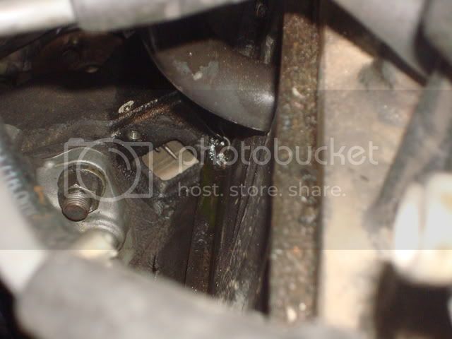
"with line mark" - "this is the mark to use"

take cover off to clean and paint line mark on the "flywheel pictured" - very simple to do but will make seeing it easier

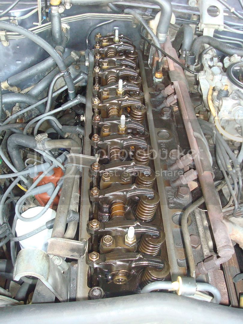
where to use feeler gauge - will slide under just move the arm and you can tell where it will slide under the arm at

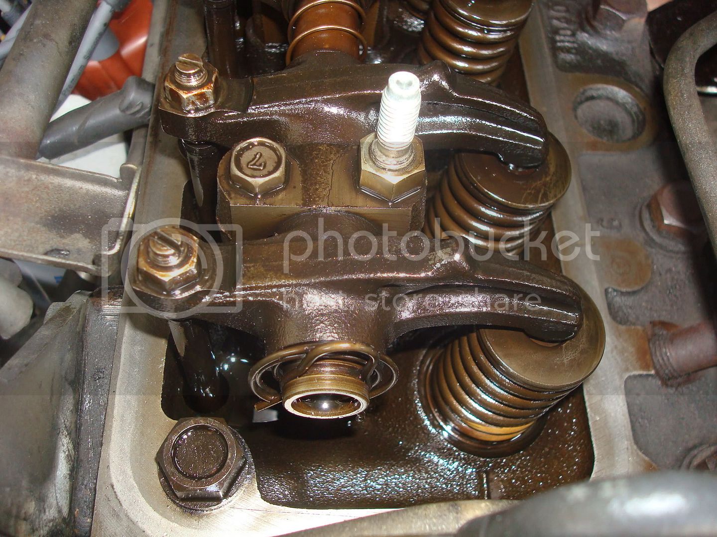
remember to stay in the correct order while using the feeler gauge for measuring the intake valves set at .008", and the exhaust valves at .014" (order is pictured in the haynes manual - i believe under section 2A)
valve cover with new aluminum paint (update: 11/13 dont recommend painting scratches very easy i should have buffed it instead)
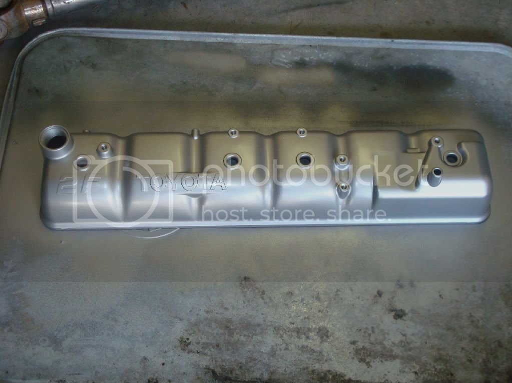
update pic added 11/13 thanks 2mbb https://forum.ih8mud.com/showpost.php?p=4300965&postcount=7

Last edited: