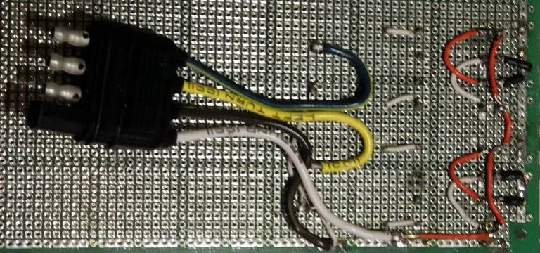
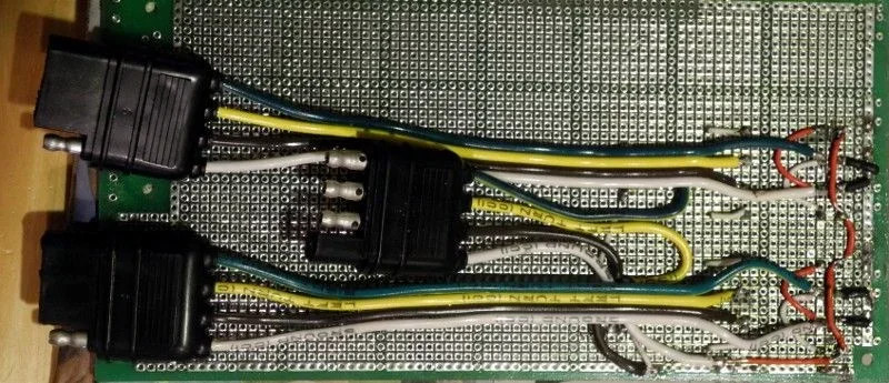
Makes interesting clicks, but not really debugged yet. It's really not as complicated as it looks. It's based upon the pdf that's floating around here somewhere, but there are two circuits for F+R. There are the two four-wire connectors for F&R lockers (motor + and -, and locked and unlocked signals) that are interchangeable in case one half the circuit ever blew a relay you could still unlock either or both F+R at the end of the trail. The third connector that is sex-reversed for clarity has 12v + and - and two wires from the F+R switches. 12v = locked, 0v=unlocked.
The 5th signal from the diffs is the "locked" light. Those will bypass this board and go directly from the cables to the lights in the dash.
The prototype board needs to be cut down and it will fit into a box that is 3x3.5x2".


The white relays are SPDT, which select one or the other of the smaller ones with the clear covers. They are DPST. One or the other is always selected based on the switch being 12v or 0v.
The white and green of the outer cables are the motor leads, so the locking or unlocking relay can set the motor to +- or -+.
Finally the negative for the unlocking relay is the locked signal from the diff and the negative for the locking relay is the unlocked signal from the diff. When the diff is locked, the unlocked signal goes away, the locking relay is disabled so the motor is disconnected. The converse is also true.


The 5th signal from the diffs is the "locked" light. Those will bypass this board and go directly from the cables to the lights in the dash.
The prototype board needs to be cut down and it will fit into a box that is 3x3.5x2".


The white relays are SPDT, which select one or the other of the smaller ones with the clear covers. They are DPST. One or the other is always selected based on the switch being 12v or 0v.
The white and green of the outer cables are the motor leads, so the locking or unlocking relay can set the motor to +- or -+.
Finally the negative for the unlocking relay is the locked signal from the diff and the negative for the locking relay is the unlocked signal from the diff. When the diff is locked, the unlocked signal goes away, the locking relay is disabled so the motor is disconnected. The converse is also true.
Last edited:
