
LOL. I'm lucky if I remember what I had for breakfast. No worries.Well thanks for the good info John I did my troubleshooting after my cruise control was all fixed like I said I had heard about the brake fluid level and I wanted to see if it cause the cruise control to not work I don't remember everything it was a couple years ago
Navigation
Install the app
How to install the app on iOS
Follow along with the video below to see how to install our site as a web app on your home screen.
Note: This feature may not be available in some browsers.
More options
Style variation
You are using an out of date browser. It may not display this or other websites correctly.
You should upgrade or use an alternative browser.
You should upgrade or use an alternative browser.
cruise control trouble
- Thread starter mr jits
- Start date
This site may earn a commission from merchant affiliate
links, including eBay, Amazon, Skimlinks, and others.
Can confirm that TI hall effect sensor can be directly soldered onto speed sensor wires. I potted this in the old housing with clear epoxy and checked everything throughout the process with a multimeter. Incredibly satisfying and inexpensive fix for this particular cruise control issue on '91-'92 3FE 80s.Im just sharing my findings here trying to learn.
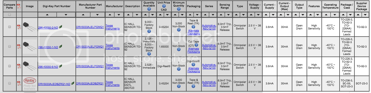
here is the data sheet for the same pickup i found on digikey. it is the one for automotive use.
http://www.ti.com/lit/ds/symlink/drv5033-q1.pdf
I am assuming that when cruise is "on" you should have power +12v and one ground and one wire that goes to the cruise control computer.
here is from the data sheet looks like a resistor may be needed but Im not sure ??? could someone please share some input.
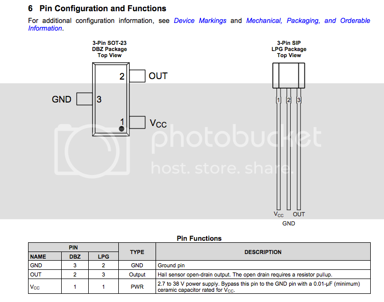
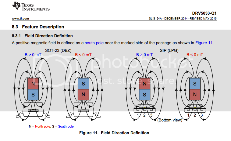
I am also guessing that a soldering this to a board may be not needed. you just need to get the sensor facing the right direction to pickup the magnetic field. and repot the case to waterproof like factory.
I know this was a few years ago, but do you have any extras? I'm chasing a fix for my '91...I got 20 free samples of this sensor/switch on the way (We have a huge circuit board fab shop at my work). If you have a .gov or .edu e-mail address you might be able to get one or two through texas instruments. I have a used sensor from cruiseryard on the way and if it doesn't work I'll use the samples to make one of these.
I know this was a few years ago, but do you have any helpful info on purchasing a new sensor? I think I can complete the repair, but stuck on locating the correct electrical sensor. I'm no electrical expert by any stretch; I don't even have a local Radio Shack to visit...I forgot about this thread, but I wanted to follow up with it. Several months ago I had my father-in-law give me a hand with soldering the sensor. He did the same process as I used, but instead used a small piece of circuit board to solder to. I am not sure if the issue was that I am a not very good at soldering so I overheated the chip possibly, but it works great now. I think it hits the minimum somewhere around 25-30. Works exactly like it should. I have about 6 or 7 more of those sensors laying around. 100% worth the money, even if you have to find someone to give you a hand.

Cheers!
I ordered the TI hall effect sensors from www.digikey.com. I got 5 of them and it cost about $12 including shipping.I know this was a few years ago, but do you have any helpful info on purchasing a new sensor? I think I can complete the repair, but stuck on locating the correct electrical sensor. I'm no electrical expert by any stretch; I don't even have a local Radio Shack to visit...
Cheers!
item #296-38520-ND
Here is the link:
DRV5033AJQLPG Texas Instruments | Sensors, Transducers | DigiKey
Order today, ships today. DRV5033AJQLPG – Digital Switch Omnipolar Switch Open Drain Hall Effect TO-92-3 from Texas Instruments. Pricing and Availability on millions of electronic components from Digi-Key Electronics.
Thank you for the info- will order, and see how it goes from there!I ordered the TI hall effect sensors from www.digikey.com. I got 5 of them and it cost about $12 including shipping.
item #296-38520-ND
Here is the link:
DRV5033AJQLPG Texas Instruments | Sensors, Transducers | DigiKey
Order today, ships today. DRV5033AJQLPG – Digital Switch Omnipolar Switch Open Drain Hall Effect TO-92-3 from Texas Instruments. Pricing and Availability on millions of electronic components from Digi-Key Electronics.www.digikey.com
Cheers!
OK, finally pulled the speed sensor & got everything stripped out. If my understanding is correct, when re-potting the new sensor, the orientation would be close to, and facing the aluminum wall where the magnet rolls with the speedometer cable (see pic below).
According to Post #18:
Red = Output
Black = GND
Yellow = Vcc
@proteolytic , any help/advice/clarification?
Thanks!


According to Post #18:
Red = Output
Black = GND
Yellow = Vcc
@proteolytic , any help/advice/clarification?
Thanks!
How did this work out ? Mike
Did not solder yesterday- hopefully today…How did this work out ? Mike
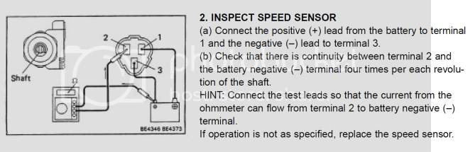
That looks about right. I connected a multimeter to it (as described in FSM or first page of this thread but I used a 9V battery because it was convenient) and tested it each step of the way. I found that the sensor needed to be right up against the housing you circled in the picture. Once connected to the multimeter I would rotate the little rod to make sure it turned on and off the signal. Once I was pretty confident that it worked I epoxed the sensor to the housing - getting it as close as I could to the sweet spot. Take your time and test with the multimeter at each step. I first tried with some off-brand hall effect sensor and it didn't work, but the TI one listed in the first page tested and worked out fine.OK, finally pulled the speed sensor & got everything stripped out. If my understanding is correct, when re-potting the new sensor, the orientation would be close to, and facing the aluminum wall where the magnet rolls with the speedometer cable (see pic below).
According to Post #18:
Red = Output
Black = GND
Yellow = Vcc
@proteolytic , any help/advice/clarification?
Thanks!
View attachment 2848874
View attachment 2848883
Thank you for the quick reply! It confirms my thought process in working things out.That looks about right. I connected a multimeter to it (as described in FSM or first page of this thread but I used a 9V battery because it was convenient) and tested it each step of the way. I found that the sensor needed to be right up against the housing you circled in the picture. Once connected to the multimeter I would rotate the little rod to make sure it turned on and off the signal. Once I was pretty confident that it worked I epoxed the sensor to the housing - getting it as close as I could to the sweet spot. Take your time and test with the multimeter at each step. I first tried with some off-brand hall effect sensor and it didn't work, but the TI one listed in the first page tested and worked out fine.
From what I could tell while disassembling the sensor, the wires were tied into a small circuit board, sitting on edge (red line in picture) and the sensor module attached to the board around the green circle area. Most of it all came out in pieces, so I never had a truly good look at it, as it was encased in the plastic housing.
In the above picture, I have used a dremel to remove the post/clips that held the circuit board in place. My thought is to re-use the plastic housing and make the fix as 'original' as possible, re-using the rubber boot that affixed the wiring harness to the sensor housing. I think I will need to extend some small wires to get a decent route and have room to locate the new sensor, as the existing wires without a circuit board are rather short. After that, I can test for function. I have several new sensors, so if I fry one or two while learning how to solder these little buggers, so be it. I may be awhile, as my eyes are getting old and tired, especially by the end of the day. Was planning on tackling it tonight, but I'm done. I'll keep posting as I make progress.
Cheers!
You did a better job at cleaning out that plastic housing than I did. Mine was obliterated by me because the whole inside only came out in chunks. Yes, the wiring is pretty short. I think I added in an extra inch or two of wire length to give me some room to do all my work. That should clean up nicely for you.
fj80 cruise control speed sensor - https://forum.ih8mud.com/threads/fj80-cruise-control-speed-sensor.1044131/#:~:text=fj80%20cruise%20control%20speed%20sensor
try my thread about this. i think you'll like it.
try my thread about this. i think you'll like it.
A good option if one isn’t into the DIY option. I’ll keep it in mind if I can’t make this work.
Cheers!
Cheers!
A good option if one isn’t into the DIY option. I’ll keep it in mind if I can’t make this work.
Cheers!


@proteolytic , did you use an old-school meter, or digital multi-meter for the test? I think my digital may be too slow to pick up signal...(?)
I realized that I have been assuming that there is a magnet(s) within the sensor housing that the hall sensor picks up when rotating. It looks like it is a press out for disassembly; has anyone popped one open to check it out? When examining the test procedures in the FSM, my understanding is that I should have continuity (4) times per revolution of the shaft. My test with a digital meter is not picking up any changes, no matter where I place the sensor in the housing. Makes me wonder if there is potential for the issue to be within the housing assy? I may have to go out & see if I can pop it loose...
Or just buy the Aussie replacement. Thx, @76lcmike.
Last edited:
I used a digital multimeter and just turned the rod in the speed sensor housing nice and slowly until the voltage dropped. You may want to first just check that you have the sensor connected correctly by directly testing it with a magnet (connect the battery and multimeter direclty to the sensor). I remember playing around with it (on both faces of it) with a magnet to confirm that it worked.@proteolytic , did you use an old-school meter, or digital multi-meter for the test? I think my digital may be too slow to pick up signal...(?)
I realized that I have been assuming that there is a magnet(s) within the sensor housing that the hall sensor picks up when rotating. It looks like it is a press out for disassembly; has anyone popped one open to check it out? When examining the test procedures in the FSM, my understanding is that I should have continuity (4) times per revolution of the shaft. My test with a digital meter is not picking up any changes, no matter where I place the sensor in the housing. Makes me wonder if there is potential for the issue to be within the housing assy? I may have to go out & see if I can pop it loose...
Or just buy the Aussie replacement. Thx, @76lcmike.
Hmm... I have tried all of the above with no luck.I used a digital multimeter and just turned the rod in the speed sensor housing nice and slowly until the voltage dropped. You may want to first just check that you have the sensor connected correctly by directly testing it with a magnet (connect the battery and multimeter direclty to the sensor). I remember playing around with it (on both faces of it) with a magnet to confirm that it worked.

I suppose I could have wired/tested it incorrectly... As I have stated before, electrical stuff is not my bag; was hoping to get a 'easy' win. $130 for an already-engineered-plug-n-play is sounding REALY good.
Crap- just realized my testing mistake: VOLTAGE, not Ohms
I'm an idiot. Will pull out parts later and re-evaluate.Thank you for your time and help.
Last edited:
Looking over page 1 of this thread Ohms (conductivity) should work as well (looking at infinite resistance to low resistance). On the sensor you should be connecting + from battery to Vcc of sensor, - to GRD on sensor. Then connect the + lead of the multimeter to Out on sensor and the negative to the - on the battery (two things are connected to - on battery). FSM says to measure conductivity (ohms) and that is what I most likely did. Put a magnet right up to the face of the sensor (or push sensor right up against metal housing and rotate magnet. If that doesn't work try the other side/face of the sensor. You did get the Texas Instruments brand TO92-3 sensor, correct?Hmm... I have tried all of the above with no luck.
I suppose I could have wired/tested it incorrectly... As I have stated before, electrical stuff is not my bag; was hoping to get a 'easy' win. $130 for an already-engineered-plug-n-play is sounding REALY good.
Crap- just realized my testing mistake: VOLTAGE, not Ohms
Thank you for your time and help.
T092-3 sensor, check. Today got away from me due to starter swap and attempted alternator replacement... I will re-do the FSM tests soon to get myself sorted out.Looking over page 1 of this thread Ohms (conductivity) should work as well (looking at infinite resistance to low resistance). On the sensor you should be connecting + from battery to Vcc of sensor, - to GRD on sensor. Then connect the + lead of the multimeter to Out on sensor and the negative to the - on the battery (two things are connected to - on battery). FSM says to measure conductivity (ohms) and that is what I most likely did. Put a magnet right up to the face of the sensor (or push sensor right up against metal housing and rotate magnet. If that doesn't work try the other side/face of the sensor. You did get the Texas Instruments brand TO92-3 sensor, correct?
Thank you!