Barn Rebuild: The family heirloom

This site may earn a commission from merchant affiliate
links, including eBay, Amazon, Skimlinks, and others.

Now repeat all that again, this time not breaking the retaining clips so you can get a better pic for your Internet thread:
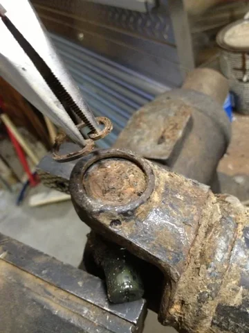
image-4248171124.webp

Drive cups out, clamp in the vise, wiggle free. Wash, rinse, repeat.

image-1780807910.webp


Images for how to install a u-joint might come later, but I don't have new parts right now. Also, I need to clean/paint the old parts. Stay tuned...
image-4248171124.webp
image-1780807910.webp
 
Well, this week I am organizing a bit. I'm also cleaning up the driveshafts for paint.

After ironing out a plan for the Land Cruiser summer budget, I am ready to start ordering parts and searching for a machine shop to clean and mill the block. Hopefully the budget is appropriate to finish the drivetrain this summer.
image-3158741668.webp
 
i've been doing ujoints the same way you're doing yours for decades. only took one to a shop...it was seriously frozen in there.

and the holes for the factory twists were on both hardtop and soft top models until at least 1974.
 
Well, stay tuned people. I just ordered U-joints, transmission and transfer case rebuild kits (decided to go all the way with this project), new TRE's, and motor mounts.

Once the engine overhaul is figured out, I'll really be making progress.
 
My u-joints arrived this week. I got out my hammer and destroyed all my pretty paint.

image-1251280935.webp
Inexpensive parts from rock auto were Japanese. Hopefully this means high quality. I have built a lot of driveshafts using stuff from MOOG boxes with success.


image-4041629004.webp


image-2520317459.webp

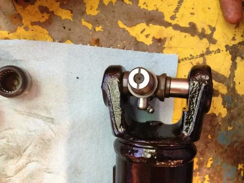
Step one: pop the caps and make sure everything is in place.
image-1251280935.webp
image-4041629004.webp
image-2520317459.webp
 
Step two: position the joint in a yoke. Make sure that if the joint is equipped with a grease fitting, it will not impede full range of motion. In this case, I had to mount the grease fitting before assembly.

image-2055810331.webp

Slide a cap over one side, taking care to keep the bearings aligned. I squish a bit of extra grease into the cap before insertion to help keep stuff in place.

image-3387906056.webp

Slide the I joint into the cup so the bearings don't fall out of place and use a hammer to drive the cup through the yoke.

image-89764377.webp

Now you can insert the opposite cap without worrying about the bearings falling out of place.
image-2055810331.webp
image-3387906056.webp
image-89764377.webp
 
image-482934239.webp

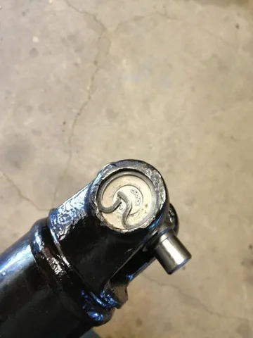
Now, use the hammer and drift to drive everything towards the center of the yoke. Install one spring clip behind the first cup you put in. You will drive everything back against that clip.


image-771126370.webp


Drive the joint into the clip. Don't hit any harder than it takes to get stuff to slide through. Once everything is centered, install the second clip.

image-2086019291.webp
image-482934239.webp
image-2086019291.webp
image-771126370.webp
 
Pics went out of order above, but you get the idea. Repeat until all of your driveshafts are rebuilt.

After assembling a joint completely, it is likely a little stiff. You need to strike around the yoke where the cups are held with your hammer so they will settle. If everything goes right, you will have free-moving joints.

I then had to shake up the spray paint to touch up everything I was beating with a hammer.

image-2220791790.webp
 
Great write-up Heirloom. :clap:

My BJ40 is still on it's original universal joints (aka "spiders") and they're still perfect. (That's the beauty of having old-school grease-nipple versions and performing regular maintenance.)

But I did replace wornout ones on my winch driveshaft using a similar method to yours and using these now-unobtainium Toyota replacement spiders:

PTO3.webp


:beer:

PS. I bought the winch second-hand and the previous owner obviously wasn't a fussy type over maintenance (like I think I am).
PTO3.webp
 
Well, stay tuned people. I just ordered U-joints, transmission and transfer case rebuild kits (decided to go all the way with this project), new TRE's, and motor mounts.

Once the engine overhaul is figured out, I'll really be making progress.

Heirloom,
When you get the t-case kit, post a pic of all the parts will you? I'm interested to compare to the kit I got and see if there are any differences. Specifically, the 3 seals that are included.

Where did you get the kit, and your cost, if you don't mind me asking?
 
I bought from CCOT. The price is online. Some parts in the kit are Toyota. Bearings are Japanese. Some stuff is Aussie. No pics this week... I'm going to go camping and come back to the trans/transfer rebuild later.
 
Engine disassembly: the connecting rod bearings are damaged. According to pictures in a Haynes Chevy rebuild manual, this pattern is consistent with sustained too-high RPM operation.

And now I ask the experts. Do you concur with my SWAG (scientific wild a.. guess)?
image-2212446919.webp
image-1877389670.webp
image-130963313.webp
 
These are characteristic of the crank wear from the connecting rod bearings.


image-3318657190.webp

#3 above.


image-3901179757.webp

#6 above.


Note: the engine assembly turned smoothly by hand. I never tried to start it before disassembly. I just put oil into the cylinders and ran a compression test.

I'm going to buy a gallon of evaporust and fill the water jackets today. We will see what happens. I want to reuse as much of the original parts as I can. Once things are clean, I'll take stuff to a machinist and have everything measured.

The cylinder walls a are very faintly stepped from the compression rings. I hope they are in spec to reuse the pistons without having to over-bore.
image-3318657190.webp
image-3901179757.webp
 
The cylinder walls a are very faintly stepped from the compression rings. I hope they are in spec to reuse the pistons without having to over-bore.

Never mind this statement. It looks like one of the #6 oil rings chunked. Resulting damage:


image-1913016613.webp

Note upper oiling ring is missing pieces. #6 piston.


image-2606113768.webp

Cylinder wall #6.

These are phone pictures. Let me know if the resolution is clear enough for you to see what is going on.
image-1913016613.webp
image-2606113768.webp
 
Piston skirt for #6 is slightly scored on the side that had the ring damage. The ring was stuck and not floating.

image-3782659890.webp

^^^Damaged side ^^^


image-235104437.webp

The opposite side of the same piston has wear patterns similar to the other pistons.


Upon further scrutiny: here is #5 piston. Similar, albeit less severe oil ring failure.

image-2433252032.webp
image-3782659890.webp
image-235104437.webp
image-2433252032.webp
 
Cylinder wall damage.

#5 first:

image-1690739014.webp


#6 second:

image-2695081062.webp


Okay, expert engine builders, help me assess and measure the damage as best you can from the pictures. Seems to me that an over-bore is necessary. This means new aftermarket .020 pistons.

How about crank damage? Is the wear very bad? See above posts for pics. I haven't pulled the crank from the block to look at the main bearings yet. Seems like the connecting rod bearings absorbed most of the damage.
image-1690739014.webp
image-2695081062.webp
 
Camshaft conditions are pictured below. There is some pitting on the fuel pump lobe. No other pitting as far as I can tell. What say the experts? How would you describe the condition of this thing?
image-1575049357.webp
image-4222747741.webp
image-2855311750.webp
 
Heirloom,

In my humble opinion, you might start a new thread with these questions. I think you'll get a lot more specific answers. I'm finding the same thing - general status in the build thread, specific tangents in a new thread gets deep and immediate responses.

EDIT - put the link in here to the thread, I want to see the answers.
 

Users who are viewing this thread

Back
Top Bottom