
Navigation
Install the app
How to install the app on iOS
Follow along with the video below to see how to install our site as a web app on your home screen.
Note: This feature may not be available in some browsers.
More options
Style variation
You are using an out of date browser. It may not display this or other websites correctly.
You should upgrade or use an alternative browser.
You should upgrade or use an alternative browser.
'77 FJ40 - Gear Reduction Starter & Dizzy Upgrade
- Thread starter GA Architect
- Start date
This site may earn a commission from merchant affiliate
links, including eBay, Amazon, Skimlinks, and others.
Thx all for inputs and advice... waiting a little warmer weather to get this installed. GA Arch. does the white female connector in your photo also fit the connector on the new starter? Or did you put on a new connector?
- Thread starter
- #63
Bill - I have not installed my new GR Starter yet. I believe the BW Ignition wire, with it's female connector is a plug and play on the new GR Starter, but not 100% sure of that though.Thx all for inputs and advice... waiting a little warmer weather to get this installed. GA Arch. does the white female connector in your photo also fit the connector on the new starter? Or did you put on a new connector?
Maybe someone else who has installed their GR starter could verify this?
Bill - I have not installed my new GR Starter yet. I believe the BW Ignition wire, with it's female connector is a plug and play on the new GR Starter, but not 100% sure of that though.
Maybe someone else who has installed their GR starter could verify this?
Yes it is, simply plug-n-play.
@GA Architect Rick - thanks for this thread. I just did both upgrades and your wiring diagram make them easy. Now to figure out how to get back the rpm gauge. I think was was hooked up to the igniter
Tachometer will generally just connect to the negative side of the coil. Thats how mine is connected. If you have an FJ60 I believe there is a resistor that needs to be installed if using the factory tach, I have seen that referenced elsewhere in the forums here.@GA Architect Rick - thanks for this thread. I just did both upgrades and your wiring diagram make them easy. Now to figure out how to get back the rpm gauge. I think was was hooked up to the igniter
Thanks. I figured that out after I posted. All good now.Tachometer will generally just connect to the negative side of the coil. Thats how mine is connected. If you have an FJ60 I believe there is a resistor that needs to be installed if using the factory tach, I have seen that referenced elsewhere in the forums here.
Old post, but post 64 says to run the small BW wire from the starter area to the relay pin #85. The wire supplies full voltage to the relay during cranking. It gets power (from the bigger BW wire) only when the key is in the start position. See wiring diagram below (compliments of Coolerman and MSPaint).Spike - It is that thread that prompted me to draw a diagram. I couldn't figure out Mr. Toad's post #64 from that link, back in 12/2009. I couldn't follow along his written directions, and I wish there was a schematic wiring of that switch. So I kept searching. Then I happened across this from Mr. Jim C. on the thread, see post #2 from 5/2014. It was a much simpler approach.
Mr. Toad adds a switch & Jim C. caps off the coil wire to the starter...............Are these both right or does one supersede the other? Hence this thread.
If adding the switch is correct, send me a wiring diagram and I'll update my original post........
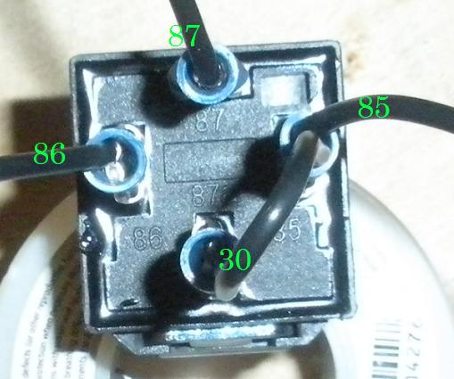
85 - +12 volt in from..."brought up from big BW on small BW".....That is the statement I don't understand.
30 - comes in from 85
86 - goes to ground
87 - goes to (+) of coil terminal
What connects to the starter?
Worked great.
What connects to the starter? Same as before. But it's not really about the starter: the point is to supply the coil with full voltage while cranking.

Last edited: