Builds 550hp 2JZ 1978 RN28L Build (1 Viewer)

This site may earn a commission from merchant affiliate
links, including eBay, Amazon, Skimlinks, and others.

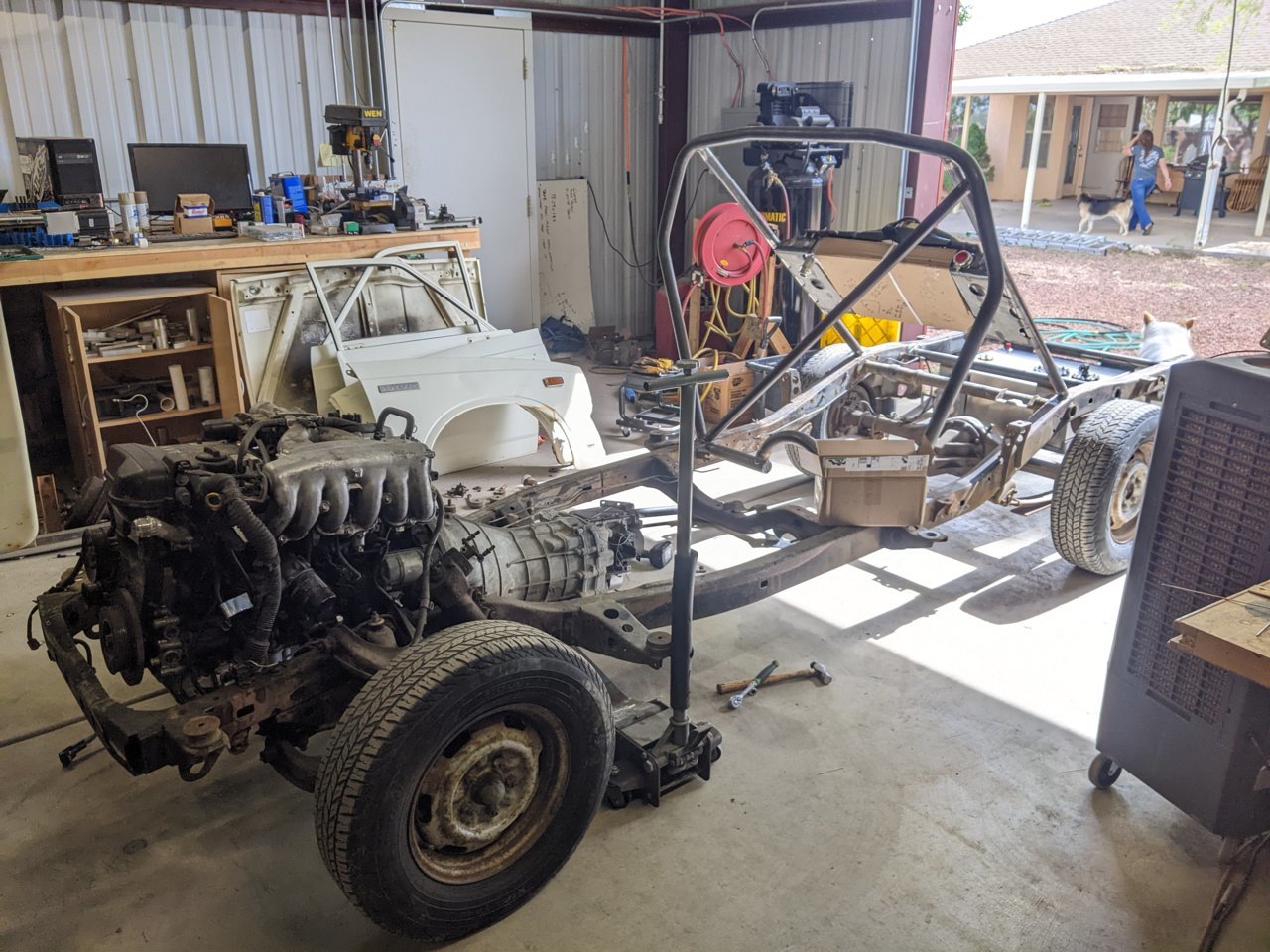
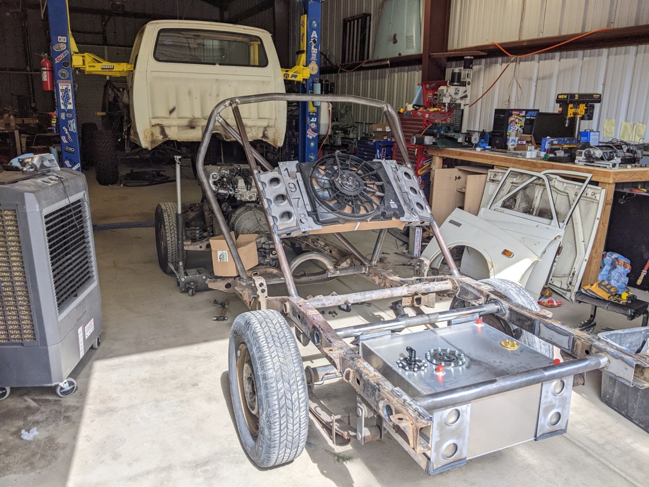
Chill weekend of some basic wrenching. Started off installing the shifter, so rolled the chassis out. If the body is ever destroyed I'm turning it into a Hilux-cart
:D


PXL_20220528_161814242.jpg


PXL_20220528_161828508.jpg


The shifter involved pulling the tail housing off the transmission.
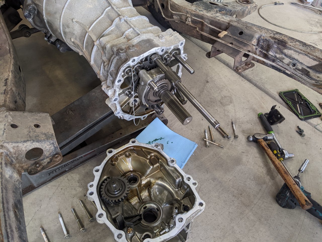
PXL_20220528_164600482.jpg


Then cutting the shaft for the shifter in half and installing these machined parts.

PXL_20220528_195048839.jpg


This allows the shifter to come straight down through the access port. The detent pin relocation bracket on the right didn't really line up with anything so I put it on the mill, made the detent stick out (engage) further and had to slot the ears to scoot it over more. After installing and reinstalling like four times and having my wife spin the engine to test that I could actually shift into gears, it was done!

PXL_20220528_200756210.jpg


The only manual I've owned is the FJ, and if has like a foot of motion in a three foot long shifter and is nice and smooth. This thing seems really tight by comparison and is REALLY short. Like there's literally an inch of motion between 1st and 5th. I think I remember reading that it shortened the shifter throw, I don't know how a stock 350z is since I never received the stock shifter, and this is the only front relocation kit I found, but holy s*** it's gonna take some getting used to. I can't even tell where reverse is either, it's someplace to the right of 6th I know and I've gotten it to engage but sitting there I can't figure out how the hell to consistently get into reverse. I mean 6th is like 1/2" to the right of 3rd, so reverse must be like 1/8" further right? It's ****ing weird, Im hoping with the engine running and stuff spinning everything will shift nicely. I might have to open it up and clearance the housing or that machined canoe thing to make sure I'm getting enough lateral motion but I have no idea hahaha

Anyways! I pieced the fuel system together, as always there was stuff I ordered wrong or still needed. Somehow I ordered all ORB-8 male fittings for the cell even though it needs AN-8 females, no idea how I totally ****ed that up.

PXL_20220528_220414481.jpg


I guess I didn't take any photos but I ran the cooling lines. I had bought 2x 10ft lengths of AN20 line and that's literally the exact length of the drivers side and has maybe 4" to spare on the passenger side
:D
it's so tight to the point I bought some different end fittings, and another weld on bung to try and adjust the water outlet on the drivers side of the block to point it more backwards to gain a few inches. Each of those lines was $250 so I'm going to the effort to make the 10ft length work since buying another longer line and then shortening it to 10ft 2in will cost a metric assload hahaha

Moving on, I started setting up the brakes and clutch pedal. I first made this bracket to hold all the reservoirs and stuff.
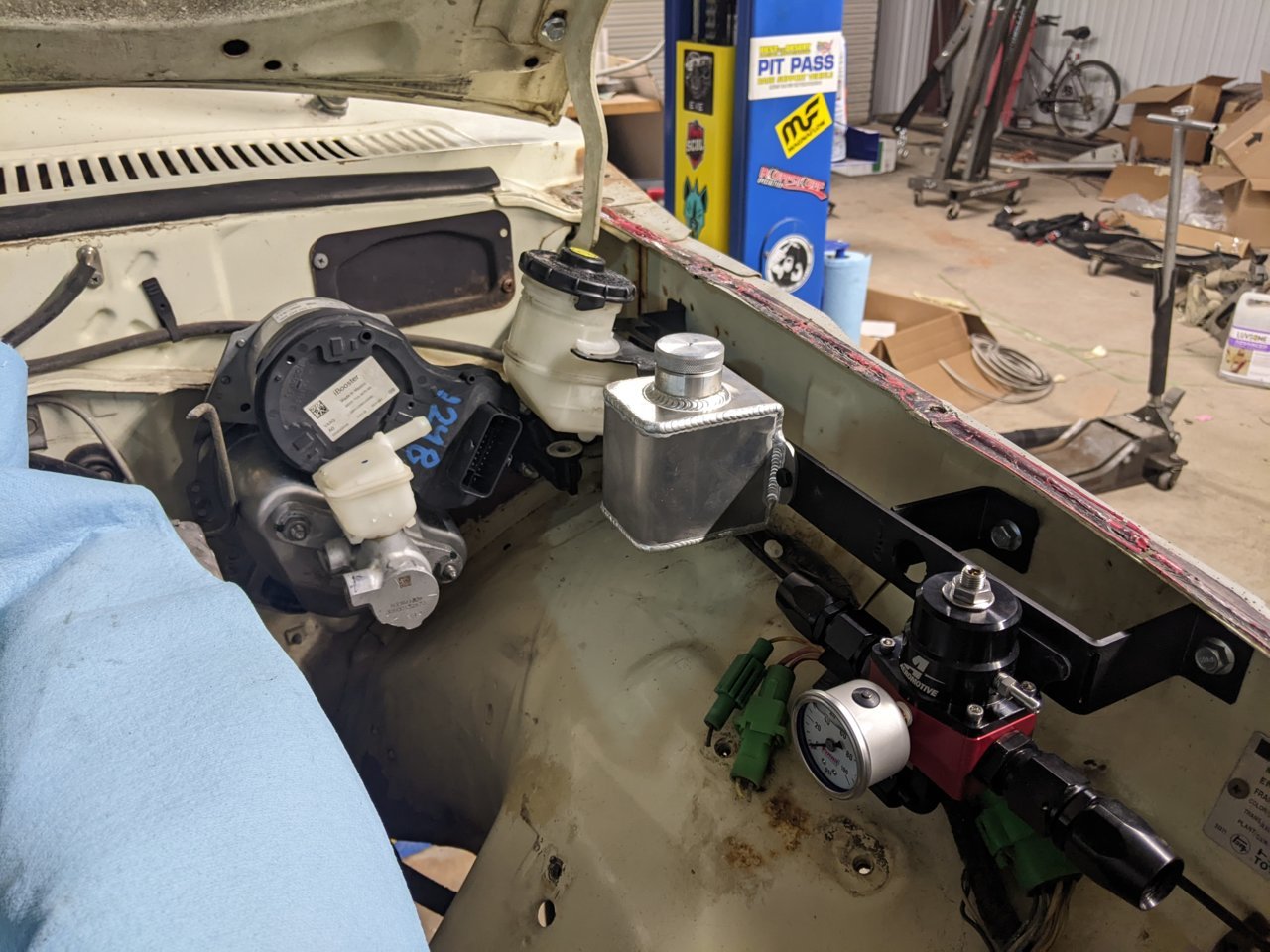
PXL_20220529_214420769.jpg


I ended up not mounting the brake reservoir there since the hood hits it plus it's kissing the brake booster. I actually still haven't figured out a nice place to put it, since keeping it slightly higher than the brake booster is a pain. Some people machine custom mini resis that replace that little plastic housing on the booster, maybe do that? Or maybe that little plastic housing holds enough and I can skip the remote reservoir? There's also a Tesla Model S reservoir that fits but is like $100 on eBay and would direct mount to the booster.

Speaking of which, I found the plugs in a kit in the US for the booster so ordered that. This is a Bosch ibooster gen 2 off of a Honda Accord and all it needs is 12V to give boost, no vacuum or anything. I drilled out the firewall for the studs and it fit right up! Very excited about this, the Hilux will have the most modern brakes of anything I own! Maybe will upgrade the FJs booster to this too.

The silver reservoir is for the clutch. And then there's the fuel regulator too.

Next I pulled the intake off to replace the spark plugs and ended up deleting every vacuum line I could, pulling the intake apart completely and removing this weird ass valve and then scrubbing it and trying to clean it up.

PXL_20220531_014634594.jpg


PXL_20220531_014644920.jpg


Waiting on the spark plugs now and a PCV. I also received a serpentine tensioner which was missing from the engine, and bought a replacement pulley for it since I had to change the belt routing since I'm not running AC or PS. I installed that today so the serpentine is now on. Also ordered some vacuum line plugs so just need to cap everything off and put spark plugs in and the engine can be wired up. I still need to figure out the exhaust too, I chopped the stock one up a bit and cut the cats out but will need a bit more massaging to stuff the exhaust manifolds in.

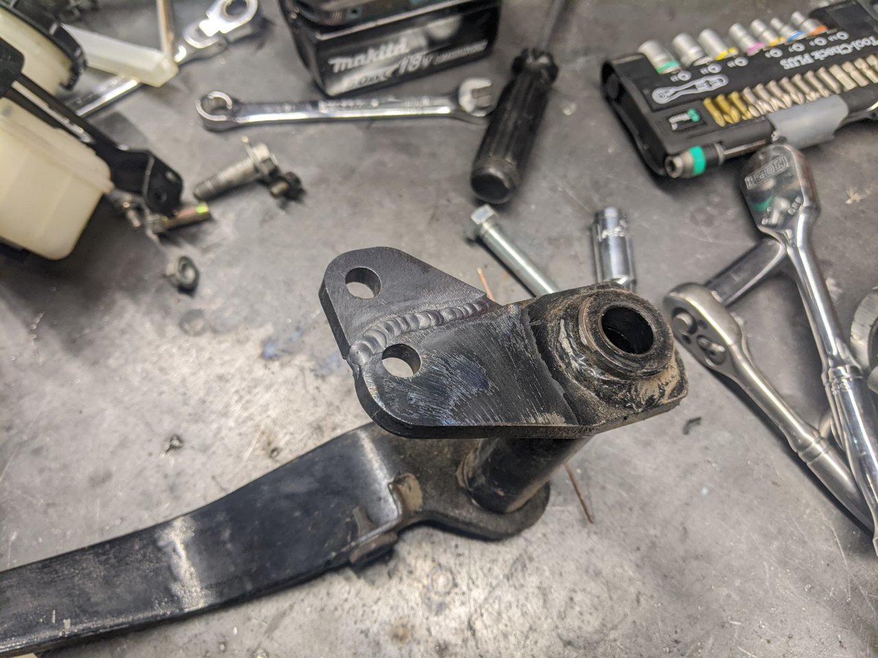
Let's see.... I had to modify the brake and clutch pedals, for now keeping all the stock hardware. I had to install a threaded spacer for the clutch pedal since the wilwood master is a lot shorter than the stock one I guess. I also cut the clutch pedal up and pushed it 6" to the left. For some reason the stock clutch pedal was like below the steering wheel? Really weird. The brake pedal was in a good spot but I had to install a little extension piece to line up with the brake booster. The booster doesn't have a threaded rod so couldn't install a coupler to extend it so just welded a blob on the end to extend it.
PXL_20220601_011212545.jpg


PXL_20220601_012538545.jpg


I have an order from summit showing up tomorrow for the fuel, clutch, and brake fittings I'm missing. Also pulled measurements for the driveshaft so hopefully get that on order locally tomorrow. Ordered some 8deg axle shims to set the rear caster for the driveshaft. Huge order of Deutsch connectors and wiring and fuse block stuff--i think I'll rewire the entire truck at the end of the day. And a bunch of other random s*** on order. I have high hopes this is the last set of orders to get the truck driving, I know I need some more stuff like a throttle cable so probably one order left to really "finalize" it for the first drive. Getting super close! A lot of this is just tedious stuff of unbolting and fitting and measuring over and over, but as of today it's almost entirely plumbing left (and then Jerry rig some wiring).

Lots of talking in this post, not a lot of pictures or cool stuff, but that means we're getting close!
 
Big post! I've still been working on the Hilux everyday since the last post, but getting into little details and wiring and plumbing so not much stands out day to day.

I had been hoping to have the engine fire up last weekend, and long story short all IS300 have immobilizers so the engine wasn't gonna fire up. I ended up sending the ECU off to a place called Quantum Auto in California and they can remove the immobilizer and do some other tweaks to the ECU. I should be getting it back next week. Other points to note was one coilpack and one spark plug wire were totally dead too, so that didn't help with the troubleshooting. Additionally, the compression for 1-6 is 150, 140, 130, 90, 70, 150. So cylinder 5 is pretty fried, as is 4. I am going on the assumption the engine will run, since I don't want to tear into it right now and I'll be rebuilding it eventually anyways.

PXL_20220606_231629955.jpg


This shows what an entire weekend resulted in. Less than two handfuls of wires going to hot or ground is all that's needed to run the ECU assuming the immobilizer doesn't kill it. I am currently wiring up the truck and all of this will look much nicer, don't worry!

Other things I've done: I ended up needing to buy a yoke and a different flange for the driveshaft. I dropped the 1350 yoke and the 1350 trans output off at a place last week so should be getting a driveshaft soon hopefully. The diff is angled down pretty bad relative to the transmission since the tranny is laid back quite a bit, so I ended up buying some 8deg axle shims and will be installing those to lift the pinion.

PXL_20220606_234507226.jpg


I added a coolant reservoir, I don't think I mentioned it before but I also modified the cooling system inlet and cut off the previous AN bung and welded a new setup on that makes the cooling lines go in a nicer direction. The cooling system is fully plumbed and currently filled up.

PXL_20220606_231600471.jpg


Because it's a rear mounted radiator it makes bleeding a bit difficult. To do this I have this pretty ghetto T fitting with a schrader valve coming off the head. The two ports I connected normally go to the heater core, though I don't entirely trust the heater core nor do I need heat over the summer so I just tied the two ports together. This gives a high point on the engine to bleed air from easily. I will eventually do something sexier, but it'll work for now.

PXL_20220610_204615199.jpg


Let's see... the fueling system is also fully plumbed and functional and running (had to do that to try and get the engine to run). The A1000 pump even in the tank is wickedly loud! It pumps through an AN10 line to a fuel filter on the frame rail, then to a regulator which has a 6AN return line and then a 6AN outlet that runs straight to the fuel rail (the 2JZ is nominally a returnless system). I put the fuel filter right behind the cab so it's easy to access.

PXL_20220606_231614707.jpg


One of the big issues I've been thinking about is the brake fluid reservoir, which the one from the Accord sits too high to really fit anywhere and still have the outlet be above the master inlet. To fix this I machined a new inlet, and decided that the clutch reservoir would double as the brake reservoir.

PXL_20220610_002824962.jpg


PXL_20220610_022609420.jpg


The mill was being a bitch and it's been awhile since I've programmed the CNC so some stuff got a little ****ed but it ended up alright and seems to work fine. Below is the one I made, and on the right is the stock mini reservoir that the main reservoir feeds. Using the stock mini reservoir would result in needing a main reservoir a good 2" higher than what I made! Luckily the little sealing nipples had a stepped rubber boot, so even though I ****ed up the top stepped portion the base part I could still use. Additionally there's a roll pin that holds the part down, so I clamped it lightly on the truck and installed the roll pin so the top of the rubber boot is doubling as an o-ring where as the OEM part just kind of sat on top.

PXL_20220610_031840227.jpg


I then machined and welded a new bung onto the clutch reservoir.

PXL_20220610_213801172.jpg


PXL_20220610_032333436.jpg


And all plumbed up!

PXL_20220611_001221618.jpg


Quick sprint through some remaining items since I have places to be. Yesterday I tried to bleed the brakes but the flares I made seemed to universally not work so need to figure that out. Today I test fit a seat out of the Can Am and I think I'll run some PRP GT3s since they have a relatively low side bolster but are super comfy and still have good containment if I go to a track. They are TIGHT in the truck, but I think any seat will be that way, the Hilux is tiny.

PXL_20220611_194457139.jpg


I also started running wires. For the time being I'm ignoring all the lights, so have run the fuel pump, the sender, and the fan wiring. Everything is using automotive grade wiring and looms and have Delphi connectors at the major components. Additionally I bought an Optima and plan to just mount that on top of the passenger side frame rail since it doesn't really fit in the engine bay, plus the stock mounting area (that's too small) is pretty close to where the turbo will be. Once the bed sides are installed the battery will be pretty hidden, plus I'll tack weld the box shut.

PXL_20220611_224958613.jpg


And that wraps up most of the key points I think! Right now the biggest issue is the brake lines not sealing so I need to buy some parts to try and correct that, otherwise I'm hopeful that next week will be the first drive!

PXL_20220611_222643496.jpg
 
IT RUNS!!!

PXL_20220615_043303951.jpg


I will post more later but I am so excited! Spent the last two days wiring and just need to run the main power wires now (so substituting some jumper cables in
:D
) but I got the ECU back today and it would start but due after a few seconds. I gave up for a bit and was researching and read some post that a guy had his car not run since some wires were shorting in the MAF sensor and I was throwing a MAF code, so I ran out to the shop in my underwear and unplugged the MAF and TPS and igniter and replugged everything in and somehow that fixed the issue and now it starts and runs!!! And everything is run through the Hilux stock key cylinder! I'll post more pictures as I wrap up the wiring, but if I get a driveshaft this week it's going for a spin for the first time in a long time
:D
 
Little update. I got the driveshaft yesterday!

PXL_20220621_024933200.jpg


I also installed the axle shims.

PXL_20220621_024945540.jpg


And I'm pretty sure I overshot the pinion angle by double hahahaha. 8deg shim and it seems to be 4deg over, I'm not sure how that happened, but on the plus side 4deg is a lot less aggressive. I need to verify the angle by pulling the shaft, but it's definitely way off. I was also debating "lowering" the rear but the leaf pack only has two, so going to a single leaf seems wrong so I'm going to hold off on that a bit lol.

The fuse/relay box is mostly done and wired into the ecu, I'm not really sure what I'm doing so EVERYTHING has fuses. For example, there is a fuse from the ignition key to the starter relay, then another fuse between the starter relay and the ECU (which tells the actual starter to engage). It seems kind of redundant... But it seems like the signal wire has 12V and the output will have 12V so they both need to be fused. I also have big stuff going through relays. There is a large terminal that is always 12V, and then an ignition terminal that feeds everything else. But there's like feet and feet of wires under the fuse box just going around to the fuse box. I have like 5 sexy little plugs and wire bundles and then 57ft of wiring connecting fuses and relays and s***, I don't know how one can possibly make it look "good", so I think I'm going to just make a big box and the fuse box will sit on the lid essentially and the feets of wire will just kind of dangle into it. And it's not like stuff is overly long, but each fuse is two wires, each relay is four wires, even if each dangling wire is like 1" dangling down it's still a total cluster. I don't have a picture of it, I still need to wire up the brake booster and the fat ass battery cables then will show it off.

Besides installing the driveshaft and shims, I got the throttle cable hooked up.

PXL_20220621_024905296.jpg


It's kind of hard to see, but it turned out awesome. I machined a little shaft that slides onto the throttle body pivot and then the wire runs through it, and then cut out a bracket for the other side and the cable runs to the stock throttle linkage. Seems to work great!

PXL_20220621_024918526.jpg


In the next day or two I'm getting a sexy brake line flaring tool. I'm going to reflare all the lines I made to be safe, and with some luck that should be the final thing (besides finishing the wiring) to make the truck drivable!
 
It drives!!!

PXL_20220623_030811053.jpg


PXL_20220623_030759169.jpg


Those are the only two photos I have from my neighbor pulling it back into the shop, thanks to him for helping me today.

Most if not all of the front brake lines I made need to be redone, so I ended up just plugging the front outlet on the master since the rear brakes needed minimum work to get going. I also wired in the master, and ran wires from the battery up to the front and installed some little junction boxes that need to be made nicer eventually. Really that was it to make it run and drive!

The engine is a little finicky, the throttle body has a bunch of plugs running to it and is acting really weird. It's like semi mechanical so half of the pedal travel doesn't do anything and then the butterfly valve starts to move. There's a big motor that I guess moves the valve but it doesn't seem to be working for the best I can tell, which maybe explains why the engine took a bit of effort to get running (I assume the idle air control is also through the big motor?). With the exception of the weird throttle, once it warmed up a bit it ran like a charm though! Actually was more power than I was expecting considering the engine is in it's weakest possible state right now.

The brakes, albeit just the rears, work REALLY well. The electronic booster is absolutely amazing and so simple! I definitely plan to convert the FJ40 and maybe my buggy to this setup.

The transmission works great! Though reverse is hard to find. On the FJ40 I need to let the clutch out in neutral to spin the gears sometimes, I assume because reverse has no synchro, so maybe that's all the issue is with the CD009 but I'll play with it more.

Handling and steering can't say much, the tie rod barely clears the bell housing and actually hits it at the extremes but it seems like it has plenty of steering angle right now. In general the truck rode fine and everything seemed to function well.

Onto issues, which there's really only one: the thermostat didn't seem to open and the engine got pretty damn hot since the temperature sensor isn't hooked up. Its a brand new thermostat so unless I installed it backwards I'm not sure what the deal is. I'll probably just run it without it and make sure everything is good, plus test the thermostat.

The ignition stays on at 9.5V after I shut it off, and it's being powered by the ECU. I thought it turned off after awhile at one point, but need to verify and see if that's normal.

The MAF seems functional, but there's no intake temperature data from it for some reason. Not sure if it's the sensor or a wiring issue.

The coolant temperature sensor plug has a wire ripped out so I need to fix that. The ECU is setup to control the fan so that's pretty important.

I also need to mount the temporary seats I have and some seat belts.

Fix those things, get the front brakes hooked up, install the body panels and I think it'll be ready to cruise into town! I think this is the first drive in 6-7 years for the Hilux assuming the paperwork I got with it was when it ran, and now it's back in action with a 2JZ!
 
I think I got a few issues sorted! Lots of reading ahead!

First off the thermostat seems fine, so I drilled three holes in it to let water pass through. I'm guessing the jiggle valve was either in the wrong place or not flowing enough water so a cold water bubble formed at the thermostat not letting it open. There is a coolant bypass hose that comes off the thermostat housing which I would think would stop that from happening... But that's why I drilled the holes to let a bit more bleed happen through the thermostat. I had the same issue on my buggy but it doesn't have any coolant bypass off the thermostat, so we'll see if that fixes it. I was worried maybe the water pump is spinning backwards since I don't have the power steering pump or AC compressor on but I didn't change the pulley on the water pump so that wouldn't happen... Only other alternative is the water pump is utterly shot which seems unlikely too.

Onto the fun troubleshooting
:rofl:


PXL_20220624_015903456.jpg


Lots of weird s*** going on. First of all the battery was dead, so the ecu didn't apparently turn off. The ECU ignition fuse needs to be pulled to turn the ignition off otherwise it hangs out at 9.5V? It's weird. What's even weirder is the TPS sensor which is presumably the biggest issue, has 5V+ at the ground!!! Bro what.

Oh, and I went to fix the coolant temperature sensor plug only to find out that what I thought was the sensor wasn't... Or maybe it is? I'm very confused, apparently there is two sensors but only one really matters, and I'm not sure what the sensor that I thought was the ECT sensor actually does or if it's even stock, since where the oil pressure sensor is appears to be plugged and then there's this other sensor.... My neighbor thought it was a oil pressure safety switch or whatever it's called where it turns the oil light on below a certain pressure, since it's a single wire sensor. What's weird is on the diagram I saw (and I haven't delved into this heavily yet) there is an oil pressure sensor (or safety switch thing) coming off the head, and I can see where that is but it appears to just be a plug with a hole in the middle. It's almost like the wire got yanked out of that sensor, and someone installed this secondary one on the block a few inches below it. Or the one on the head isn't a sensor and is literally just a plug, but again why would it be plugged? It's rather odd. ANYWAYS, s*** is confusing, the actual ECT I found and guess what? IT HAS 5V+ ON THE GROUND ALSO.

So I unplugged the ECU, checked all the grounds which were grounded correctly besides apparently these two sensors and said **** it, pull the rats nest apart and figure out what is going on. And the issue is actually in plain sight in that photo. For whatever ****ing reason, the ground for the TPS runs away from the ECU and under the intake towards the injectors and then to the transmission (or where the automatic used to be). That section is what's draped over on the right, and at that plug there is two wires that were ripped out. And you guessed it, one of them is a ground and is the only ground wire that seems to have continuity to the TPS and as it turns out, the ECT sensor too! That doesn't answer why those ports had 5V going to them, but there is a second wire that is pulled out of that plug which I'm guessing has 5V when the ECU is connected and was "shorting" to the disconnected ground which also was never connected to ground anymore to begin with. I'm guessing that plug went to the tranny and grounded out there? It's really weird, everything else has a direct ground path and these two sensors run through a plug at the transmission I guess.

Tonight I think I'll pull the harness off the injectors and completely tear it down and delete all those wires going to the back and rewire the ground to somewhere on the intake. There's a lot of wires in the harness I don't use so I can remove quite a few while I'm this deep into it. Hopefully that will fix the throttle, make the coolant temp work which hopefully turns the fans in, maybe it'll fix the weird ignition power issue, and then hopefully the thermostat is fixed! Find out more tomorrow! :D
 
Some big strides! I tore up the harness more and cut out a bunch of useless stuff, mostly going to the transmission but also some other plugs I don't need. Also the sensor I was confused by was a knock sensor, and the oil pressure switch is off of the oil filter bracket, so that mystery plug off the head I think is literally just a plug.

PXL_20220624_202233672.jpg


It further turns out that the ground loop that went to the transmission plug originated from the body harness, most of which I didn't have connected. So the TPS and ECT grounds came from the body unlike most of the engine sensors that grounded directly to the engine or through the ECU. With that figured out I buttoned it back up, using abrasive resistant electrical tape.

PXL_20220624_211916742.jpg


PXL_20220624_211922430.jpg


Annnnnd the TPS now has no positive continuity. Fast forward a bunch and some confusion, and turns out the ECU "B" plug has a 5V reference wire that powers some of the sensors. This wire was NEVER hooked up, so I'm utterly confused as to how those sensors had 5V before. It seems like stuff was shorting and jumping around all sorts of weird. Between wiring the reference 5V to the correct bundle and taking the grounds that went to the body plugs and connecting them to the block, EVERYTHING ended up fixed! Like more stuff ended up fixed than I was trying to fix! The IAT sensor now works, the ECT and TPS works, the motor for the throttle body made a noise, all kinds of stuff now works on the engine!

All the engine codes I had disappeared with the exception of one: the accelerator pedal position sensor (APPS). The IS300 has a semi mechanical but otherwise drive by wire system, so effectively with the APPS missing it was in mechanical limp mode where the mechanical actuator doesn't do anything for the first 50% of travel and then engages, limiting power and ****ing with the idle. I'd heard about mechanical conversions so went ahead and took the throttle body apart to see what I could do. Making it fully mechanical only messes with the idle, but there's a physical idle set screw anyways so not a big deal.

PXL_20220625_005734971.jpg


PXL_20220625_005747651.jpg


PXL_20220625_010119441.jpg


Long story short, all that was needed to fix it was take that little lever above and reposition it about 30deg down and that made it all mechanical! I grabbed some steel and welded another arm onto it and I now have full throttle, zero throttle lag, and eliminated the need for the throttle body motor as well as an electromagnet!

The final thing is the truck was still overheating, even with the thermostat pulled. I thought the water pump was flowing backwards since it was sucking water towards the thermostat so the thermostat was always seeing cold water.

PXL_20220625_025332685.jpg


It turns out the thermostat is in the intake side of the engine which sounds like is somewhat uncommon? Essentially the engine recirculates coolant internally and once it gets hot the thermostat cracks and flushes cold water in which cools the engine and thermostat thus closing it, so the engine tends to run hotter since there is no bypass around the thermostat so it needs to get to full temperature before there's any water flow.

This shouldn't really affect anything since it's a closed system, but since my intake hose off the radiator is on the high side that means any air in the radiator will stop coolant being sucked to the engine--again shouldn't matter until you lose any coolant OR have an air bubble. I jacked up the drivers side so the intake hose off the radiator was on the lower side and then let it warm up and fed it the hose and that seemed to be the key! Bleeding it correctly was the issue the whole time! I took it for a drive and got gas and the hottest it got was 200 (and I don't think the radiator fan is turning on).

PXL_20220625_145855560.jpg


I had two instances where the engine died, but they were both after throttle pulls and then punching the clutch so I think it's just the rpm dropping and not recovering before it dies. The one weird thing is I seem to have to turn the ignition off to get it to restart, since just cranking it after it dies didn't work. Kind of odd, need to troubleshoot that more. But it runs and drives and doesn't overheat! Next up is get the front brakes replumbed and install body panels.
 
Almost 4 months to the day, and the biggest achievement of them all has happened, the first real drive! Got the front brakes plumber, through the panels back on, and went for a 30 mile drive!

PXL_20220628_021100760.jpg


PXL_20220628_021113262.jpg


View from inside, right now I'm using my phone sitting in the ash tray as a digital dash connected to the OBD2 port.

PXL_20220628_021957033.jpg


PXL_20220628_022005773.jpg


PXL_20220628_023144188.jpg


PXL_20220628_023157105.jpg


PXL_20220628_023206743.jpg


PXL_20220628_023244870.jpg


PXL_20220628_023220149.jpg


PXL_20220628_023227279.jpg


PXL_20220628_023257092.jpg


PXL_20220628_023357769.jpg


The trip was amazingly successful! This thing is already a blast, and will just get better!

The brakes are absolutely insane, now to be fair the truck weighs about 2300lbs (I weighed it over the weekend at 2195 with a tank of gas and no panels) and the tires are tiny and probably the cheapest 26" tires in the world--- but that electronic booster is absolutely next level and it's stupid easy to lock everything up. Maybe to the point of being dangerous if a stranger got in and drove.

I'm not sure how to wire the ECU to tell the fan to turn on, so I just plugged the ignition block into the fuse relay trigger so the fan is on when the ignition is on, and the hottest the engine got was 185 and I think it has a 180deg thermostat. Now that's not saying much, but I was worried the radiator wouldn't get any airflow and I'd still like to put some scoops under the body to grab air but it seemed like it stayed totally cool the whole time. I'm curious how hot it'll get without the fan on at speed, but the cooling system seems to be working!

The transmission is great! Though I dropped into 3rd and 4th and 5th unintentionally way more than I'd like to admit. Luckily the 2jz has a nearly 7000rpm stock redline plus I wasn't going very fast, but I'm used to the FJ40 which has only 4 gears and a lot of throw between them. Finding 6th is especially hard, though it might just be my worry of it hitting reverse and not pushing to the right hard enough. A stock transmission has a reverse lock out which my shifter got rid of, though it'll grind and not drop into reverse over a few mph obviously but it's still a fear I have. The FJ40 you have to very intentionally go into reverse, this is like a 1/4" difference between 6th and reverse. With that said the transmission is already a blast, I've never driven anything with 6 speeds and with the 4.10 rear ratio you go through all of them pretty fast if you want! 3000rpm in 6th is just shy of 70mph, so it's definitely geared a bit short. The gearing is about 30% lower than a stock 350Z rear end I think.

The steering and handling are kind of what you'd expect out of an old vehicle, but honestly comparing to the FJ again it feels great. The steering wheel seems to have a good bit of slop but it doesn't wander at all, and it brakes straight. The FJ is a bit of a work out to keep pointed straight and this thing just cruised.

The one issue I did have is right at 5000rpm the ignition turns off. This is the same issue I mentioned from the other day but now I have it figured it out. I have to fully turn the ignition off and on and then it's fine, but it's right around 5k every time and it dies. I'm thinking since I have one 30A relay powering my ignition bus bar that then powers a bunch of other 30A rated things that maybe a relay is just acting like a breaker and turning off power to the bus bar? But I think the fuel pump stays on which should turn off if the ignition goes off, so maybe it's something else. But it's definitely the ecu or igniter turning off from what I'm guessing is too much power draw for what I'm supplying at high rpm with a lot of spark. That's my theory at least. Just another one of those wiring things that needs to be done properly, hopefully. But on that note the ECU turns off and isn't drawing power after I turn it off! I don't know why it stopped doing that but it's fixed
:D


Oh and one final thing, it is INSANELY loud. It needs a muffler asap, we had to wear ear muffs for the whole drive since it's so ****ing loud. People are like I want a loud exhaust, you haven't heard loud until you have a 12" long pipe off the header flange pointed at the floorboard. God it's ****ing horrible, but it does snap crackle and pop during shifts which is entertaining
:D


Lots more to come, but today was a huge day where the truck transformed into an actually useable little toy that will now get upgraded and improved on instead of a single huge undertaking to make something functional. I can take it to lunch and keep improving it and not feel like I bit off more than I can chew with each little modification!

Thanks for reading and enjoying this milestone and 4 months of hard work!
 
I'm not sure how to wire the ECU to tell the fan to turn on, so I just plugged the ignition block into the fuse relay trigger so the fan is on when the ignition is on, and the hottest the engine got was 185 and I think it has a 180deg thermostat. Now that's not saying much, but I was worried the radiator wouldn't get any airflow and I'd still like to put some scoops under the body to grab air but it seemed like it stayed totally cool the whole time. I'm curious how hot it'll get without the fan on at speed, but the cooling system seems to be working!
I used the dual version of this on the electric fans in my FJ40. Its worked really great.

 
Last week after ****ing around with the engine more and joining an IS300 forum of which people just told me to replace the acceleration pedal position sensor which I had a CEL for, I found in the description of a YouTube video for the pedal sensor that it could cause limp mode issues. Fixing the CEL seemed like the obvious path forward since nothing else was blatantly wrong, even though there was no indication of my issue from that. The pedal position sensor it turns out has really weird wiring, and it was never connected to the ECU which seemed weird considering I was getting a CEL for it. The wiring for the sensor runs into the body harness plugs and then there's inputs back into the ECU from the body that carries those same wires. Just like the TPS and CTS, they talk to the ECU but don't directly go to it for who knows why. After tearing the harness down AGAIN just to find that all I had to do was connect two pigtails on two plugs, the pedal position sensor finally could talk to the ECU! Annnnnd that fixed it!

Again, who knows why, but the sensor being disconnected from the ECU was stopping it revving over 5000rpm. Now, an explanation of the drive by wire system: you push the pedal which pulls a cable connected to the throttle body butterfly valve. In stock form there is no motion until about 50% throttle and then as a mechanical backup the butterfly can be physically actuated. What happens is you give it throttle, the accelerator pedal position sensor reads that motion in the cable and tells the ECU which then tells a motor to move, which is then monitored by the TPS and tells the ECU it moved. So you effectively give the ECU an electronic input with one sensor, a motor moves which actuates the butterfly, and the TPS gives the ECU the output of what happened. The reason all of this is important is I had to remove the little tab I had welded on to "manually convert" the throttle body since I had fear that the motor would try to override the physical motions I'd give the throttle. On the plus side though, after some testing it seems that the actuator motor is completely dumb (thus why the TPS exists downstream of it) since unplugging the motor doesn't throw a CEL. So after reconverting the actuator to a manual setup and unplugging the motor, and having the pedal position sensor doing something (which doesn't really matter? Because the TPS is what tells the ECU that the butterfly opened...) now I have full throttle and it's all manually controlled!

That was pretty drawn out to say that today I went for the first drive where everything seemed to function perfectly! And the Hilux is an absolute blast! Bouncing off the limiter and shifting through the gears is amazing. The engine seems to want to rev and peak torque and horsepower are both at 6000+rpm, so being able to go over 5000rpm is actually quite noticeable. I even took it up to 100mph, and besides a driveshaft wobble (from installing the wrong axle shims) it felt solid. I'm probably gonna weld the rear sooner rather than later since just rolling into first or second feels like one tire is just burning out. I also think I'm going to run the exhaust to behind the cab and that should fix 90% of the noise issues. I had been considering just turboing it now on low boost to help with the exhaust but I want to run it N/A for a bit to make sure it's happy.

Here's a little walk-around video:


Then on Saturday I installed an exhaust that I had laying around from a different vehicle.

PXL_20220702_181205216.jpg


Then went for a 70 mile drive up the mountain and back down and it ran like an absolute charm and is a complete blast to drive!

Yesterday I went to my neighbors work and we dyno'd it because why not
:rofl:


PXL_20220704_220847485.jpg


PXL_20220704_221408107.jpg


And the graph:

PXL_20220704_224343935~2.jpg


160hp and 160ft-lbf. This is the first time I've ever been on a dyno, and that is the "corrected" number which I guess is what people compare with. The actual power at elevation was about 125hp/tq.

This is pretty pointless besides a baseline, so right now the truck is 125hp and weighs ~2300lb with no one in it. The one weird thing was the rev limiter was around 6200rpm and it should be at 6800rpm. I don't know if there's some other weird stock ECU thing turning it down. Im not going down that rabbit hole much since it runs completely normally otherwise, but is odd.

I'm also now back to debating just spending the $2k on the cheap turbo kit
:D
but I should stay focused on getting good seats and redoing all the wiring so it has lights and stuff...
 
It's time again for some updates fellow Hilux and/or 2JZ followers! Last update was July 5th, hell yea
:D
Not much happened through the end of the year, drove the truck around a bunch and then I was traveling a lot, did some work on the buggy, and then winter hit. I got insulation quoted in November (finally) and that involved moving everything outside or into a corner of the shop, and then they weren't able to get around to actually insulating it until a week and a half ago. So nothing happened whatsoever in the shop from about Thanksgiving to 10 days ago.

PXL_20230111_022850063.jpg


And then immediately after that I had some friends from SLC come down to work on their 4runner in preparation for KOH in a few weeks. They helped me move stuff around but organization was the extent of working on my stuff.

PXL_20230115_192154380.jpg


The shop also has a new layout, and I added a second mini pallet rack. Everything is located along the outer perimeter so there are no tables or anything in the middle, which opens it up and makes it WAY more spacious. As you can see we stuffed 5 vehicles in with room around them all and space for a few more. After everyone left, this is the current setup:

PXL_20230122_021757375.PANO.jpg


And first project up is the Hilux! I got a letter months ago that they wouldn't send me the title until I got a safety inspection since the title is from Oregon originally. Really dumb considering it's plated, registered, insured, and legally fine to drive. With that said, it won't pass safety because it doesn't have a horn or blinkers since it didn't have tail lights. So the first task is to finish the bed sides.

PXL_20230118_013443843.jpg


I had started on one side awhile ago and hadn't touched the other side at all. The one side was tacked up and that was it. I don't know if it was mentioned before, but the truck was a long bed and for the best I can tell was a short bed frame (probably one and the same frame) so the bed overhung the frame a lot. I had gotten used to how tiny the truck was without a bed, and wanted to keep it really small looking, so that started with how to mount the tail gate, which bolts to the bed originally. I made some mounts for the rear cross member (rear fuel cell cross member) and that left about 4" of the frame hanging past the tail gate, so I chopped that off. The tail gate location set the length of the bed sides which meant I had to remove 13". As you can see I made the cut behind the wheel well.

My plan was to use some alignment fins that I'd weld to both pieces to create a level plane for both pieces. The first bed side I tacked the sheet metal and then went to weld the fins, which ended up not working great. The second side I did all the tacking on the fins first and that worked much better (I ended up cutting the sheet metal tacks on the first side, but still didn't end up going as smoothly).

PXL_20230118_024346711.jpg


With the fins welded, I welded the sheet metal together which was a complete bitch as you can imagine. I welded the inside, and if there was anything weird on the outside I welded over it.

PXL_20230122_022003025.jpg


PXL_20230122_022009388.jpg


I then took the flappy disk to it. I honestly thought it'd turn out better, but the sheet metal got so warped during the process I'll have to follow up with Bondo. But that's a task for another day (or year
:D
)! Speaking of Bondo, the passenger side with the fuel filler has a metric ass load of what I think is Bondo? But the metal seems perfectly fine on the inside, and just has like a 1/4" of Bondo on the outside. I'm wondering if this was from the factory to form the body around where the fuel filler cap goes? The body appears to have similar quality on the B pillar in a few spots. I can understand it getting crunched, but the fact the bed side where it's just painted metal on the interior of the bed side shows no signs of being crunched, I'm kind of confused. Regardless, it's cracking.

PXL_20230119_024809293.jpg


Onto mounting the bed sides. I decided to keep it simple with a bracket off the roll bar that goes to three bolts on the front of the bed sides, and then make a bracket to go to a hole at the rear of the bed side.

PXL_20230123_003244951.jpg


PXL_20230123_003250063.jpg


This whole setup is actually surprisingly stiff. I need to drill a hole for the second bolt in the rear, and I think I'll add some stiffening elements to the beside itself so it's pretty floppy without the floor now, but otherwise I'm very happy with it.

PXL_20230123_004405680.jpg


PXL_20230123_004359356.jpg


And that brings us to the first time the truck has looked like a truck!

PXL_20230123_004336731.jpg


PXL_20230123_004323191.jpg


PXL_20230123_004427001.jpg


PXL_20230123_004345194.jpg


There's a bed piece that goes behind the wheel well, one side is crunched pretty bad and the other is fine. I could cut both at an angle and make them a pie shaped piece, I'm not sure if that or just leaving the piece off will look better. I could also add some wings onto a rear bumper like off-road bumps are. Speaking of which I need to do a rear bumper, and depending how that turns out I may raise the fuel cell. Right now the top is flush with the top of the frame so I can have a mini bed area, but with how far it hangs below the bed looks a little weird. It'd be easy to raise it, just cut four welds and reweld the fuel cell cradle, but then I'll have less mini bed space (hell at that point just skip the mini bed since it wouldn't be level with the frame or tail gate then).

But the main goal of having the tail lights mounted so now I can start wiring those in is complete! The bed sides will get more work, but I'm happy with how it's looking right now! And now that the shop is insulated and I have some little (soon to be big) heaters, I can actually work on stuff in the winter without hating life.
:D
 
Been 1.5 years since I last posted. Hilux got driven a bunch and a couple tweaks earlier this year.

upload_2024-4-5_14-56-56.png


In the past (maybe I had posted it) I had the Vibrant AN-20 coolant lines randomly start leaking. I had that happen AGAIN, this time on the coolant line that had been fine so far. One day I was driving the truck, next day come out and there's a puddle on the ground. The coolant lines run ~$250 a piece, and while straightforward to do, I didn't feel like replacing it and had other projects to play with. I finally pulled the trigger a few weeks ago and ordered the stuff to fix the cooling line. On top of that, I decided to fix the radiator that had the hoses going the wrong direction.


Starting with the radiator: the reason I wanted to "fix" it was the water inlet/outlet were backwards. And I can't say I planned what direction they should go in the first place, but it turns out a 2JZ has a reverse flow water pump meaning the inlet and outlet are swapped from what normal vehicles are I guess. What that meant though was the water outlet from the radiator was on the high side and the inlet on the low side, which is fine, but if the cooling systems has a leak or runs low it means an air bubble can form on the high side of the radiator and water will stop flowing into the engine, so the cooling system always needs to be absolutely topped off.

Additionally, since the radiator is at a pretty extreme angle on the rear cage, filling the radiator was a bit of a bitch. I also thought this was contributing to the difficulties I've had bleeding the cooling system, so I decided I would re-angle the filler cap.

upload_2024-4-5_16-2-7.png


I started by cutting the inlet/outlets, the radiator cap cap neck, and then used a hole saw to cut out where the drain plug was an add another hole below the radiator cap.

upload_2024-4-5_16-4-8.png


I had bought a new radiator cap neck to weld in, but ended up being able to reuse the one that came on it. I then welded a tube at the angle of the cage to make the cap sit straight up:

upload_2024-4-5_16-5-39.png


The inlet/outlet I was able to reuse and flipped which side of the radiator they were on. I then cut some filler plates on the plasma table and capped off the original positions:

upload_2024-4-5_16-6-40.png


upload_2024-4-5_16-6-54.png


It turned out pretty good! I had to make a few tweaks to the radiator hold down plates, but otherwise was pretty straightforward.

With the new hose locations, I could now remake the AN lines that had s*** the bed. This ended up turning into an absolute cluster ****. Going back to the original issue, the passenger side cooling line had started leaking originally and I had enough AN fittings laying around to swap the screwed up section with some aluminum hardline. Kind of defeats the purpose of why I wanted the AN line so I could easily reroute it in the future, but it saved me buying another expensive line. The passenger side thus ended up being a couple feet of AN-20 from the engine to a 1.75" aluminum hard line which terminated at the back of the cab, and then another 2ft or so of line from there up to the radiator. Now the goal was to fix the driver's side that had started leaking also, but this time I just went ahead and bought a new AN-20 line (from somewhere else, either Earl's or Fragola, not Vibrant again) and this one is a stainless braided line instead of the nylon braid (as if that should matter). Well it now turned out that from moving the radiator interfaces that the new 10ft AN-20 line I bought was barely too short, and the passenger side short line to the hardline was also barely too short.

Definitely not wanting to buy a 10+ foot AN-20 line, I said screw it I'll just add an aluminum hardline to the driver's side also, same thing running from the ~back of the engine to the back of the cab. Somehow I have an entire box of AN fittings that I've bought and didn't work, and just so happened to have enough AN-20 fittings and weld bungs to make the new hardline which worked out great. I build the new hardline and the new AN sections so the driver's side is good to go. Except literally while I'm under the truck working on it, the front section of original AN-20 just randomly starts leaking. You can't make this up.

upload_2024-4-5_16-15-7.png


That photo is actually wrong, because that photo is from AFTER replacing that front section and this was the replacement piece and it did the same thing and then I got the photo.

I'm standing under the truck, and it just starts dripping out of the complete blue. I wasn't near the line, I wasn't touching any end of it, I wasn't doing anything and it just started dripping through the skin. The fittings are fine, the line just s*** itself. The ONLY possible thing I could think of was I was welding tabs on crossmembers for the new hardline, and somehow it shorted through the anodized aluminum fittings into the stainless inner core and that melted everything? Though that's never happened to me with any other lines, plus when I first started having this issue I wasn't welding on the truck but had been driving it for weeks and parked it and came out to a puddle. I even talked to Vibrant Performance and they said the use case and fluids were fine and they had no explanation (or help) for $500 of hoses literally thrown away after 18 months.

Oh and it gets better. I pull the passenger AN lines to replace them, the rear being too short now and the front leaking. And of course one of the AN reusable fittings is seized up and the threads rip out. It's aluminum threads, what do you expect, I can live with that. But I've now had a fitting also get wasted by this s***ty line, and now am out of AN-20 fittings so have to buy and wait on parts to show up. Ahhhhhhh
:mad:


Anyways, eventually get all that s*** sorted out.


upload_2024-4-5_16-8-54.png


The one other thing I decided to do while I had it up on the lift was to weld the differential. I figured when in Rome, and the thing can't put power down to save its life. This was an easy hour or so task.

upload_2024-4-5_16-32-16.png


Four driveshaft bolts, four bolts per hub, and then the 3rd member bolts. Spray off with brake clean, spray off with isoproyl, and welded the spider gears together and back in she went!

I forget how fun the Hilux is when I haven't driven it in awhile, I guess all the vehicles I own are like that! The welded rear is a lot of fun, you still have to be careful getting going since it'll spin the rears easily but at least forward motion somewhat occurs instead of sitting in one spot, and its a drifting machine now! The manual steering however is an absolute pain as one can imagine. I still have a Prius power steering unit and rack and pinion sitting here to go in, with the welded rear that might accelerate the need for adding power steering.

After that I drove it around a fair bit, and then in May it went under the knife again.
 
We'll call it up till now as "Stage 0", ie getting it run into and functional. Next up will be the next stage, which is making some power baby!

After my neighbor harassed me enough, I bought a bunch of parts and they're starting to look correct:

PXL_20240505_192935628.jpg


Right now the plan is to boost the stock 2JZ, and then I'll build my spare 2JZ and hot swap it in, maybe start that once I get the boost going. Right now the plan is to run this HX30(???) my neighbor pseudo gave me which comes off a 5.9 Cummins I guess? And his logic is the Cummins is twice the displacement but maybe half the revs (not really but whatever) so it should pump roughly enough air. At least for what a stock naturally aspirated 2JZ can handle.

Realistically to boost the engine though, you need a stand alone ECU because the stock ECU can't be tuned. So I finally bit the bullet and ordered an ECU Masters EMU Black, plus a flying lead harness so it should be somewhat plug and play of just connecting the stock plugs to the new ECU.

PXL_20240505_212943651.jpg


I'm really excited for this. The EMU Black was recommended on the Supra forums a lot, and is common with import guys since it's essentially designed to run a 6-cylinder engine. It has individual spark and injector control for 6 cylinders plus VVTI control which I need (a stock turbo 2JZ is non-VVTI, but the N/A one has VVTI which I'll continue to use since modern ECUs like this can control it). After tuning Tundras and playing with Holleys a bit, I'm excited to tune the 2JZ and learn a new system. It's also extremely small, and has a built in MAP sensor, so I get to delete the MAF along with all the pseudo-drice by wire electrics.

Additionally, I went ahead and ordered some LS coil packs which apparently can fit between the valve covers and that then allows the little energizer box (forgetting what it's actually called) to get deleted since that's built into the LS coil packs. And since the stock 2JZ is a waste spark setup, so two cylinders are always sparking, this ends up converting it to a fully controlled spark setup where each cylinder has individual spark and fuel control, all while cleaning up the wiring even more!

PXL_20240505_212916620.jpg


In classic Hilux fashion, there's a combination of nice parts where it matters (imo) and then eBay slapped on it. I got an eBay intake manifold since it was like $400 including a 90mm throttle body, and then this cute little intercooler that barely fits up front. Sadly I had to cut the bottom of the core support out, but otherwise it'd be an insanely tiny intercooler or have to get fancy with where to run one. I also bought a generic piping kit to connect everything. With how it's setup the turbo will feed into the front mount intercooler and then that will dump through the throttle body and new intake, so all the intake s*** that used to cross over the valve covers is deleted.

With that said, that fancy looking intake is a bit too long so to keep the headlight intact and be able to run the boost hose, I decided to chop it up to move the throttle body back. I first cut the throttle body plate off, and then machined it down on the mill.

PXL_20240505_210508283.jpg


PXL_20240505_212851464.jpg


Next I'll cut an aluminum plate to seal it up and weld the throttle body plate back onto the intake manifold. That will oriet it and give me the space I need to clear the back of the headlight.

While on the intake topic, it came with a fancy fuel rail too and it looks like I can reuse the 650cc injectors I originally had on the buggy's LSA supercharger if I just change out the o-rings. I'll probably need to make some custom mounts for the fuel rail since LSA injectors are super short, but that should work great and for the relatively low power numbers I want I think the 650s will be plenty of injector.

PXL_20240505_212907753.jpg
 
And those two posts get us caught up to now, and two months later and we're finally making progress! My buddy dropped his buggy off and we built a wiring harness for it, I took my buggy to a race, another guy dropped off a Tundra to modify, but finally I touched it again since May!

upload_2024-7-6_17-16-8.png


First up is to finish modifying the intake, which my God I didn't realize that'd be like 90% of the fabricating needed for this phase of the build. First was welding the throttle body flange back on, which required some filler plates designed and cut out.

I do love aluminum!

upload_2024-7-6_17-17-31.png


upload_2024-7-6_17-17-44.png


Going a bit out of order here with the photos, but on the topic of the intake there was a couple other tweaks. First was welding some filler plates to the bottom which I don't have any photos, and hilariously I then found some block off plates included with the intake (maybe I should look through the box before chopping it up). I'm not sure what the ports on the bottom were for, but they're sealed up now! Next was to add an IAT and MAP sensor bung which involved a little lathe work and threw those on. And lastly was making a throttle cable bracket.

upload_2024-7-6_17-20-4.png


The welds on the throttle cable bracket were gorgeous, finishing out the intake on a high note. I briefly debated doing a drive by wire throttle body, mainly so I could have some different throttle maps to tame the truck. But throttle bodies are insanely expensive these days, a 90mm LS7 one is like $500! And this thing was already cable driven, and I have the "free" 90mm manual body that came with the intake so I'll start there.

upload_2024-7-6_17-20-32.png


I might paint the intake black, but part of me likes the aesthetic of this fancy intake just absolutely hacked and glued back together. I'm not sure how to describe the philosophy, but some tasteful performance and execution with minimal care for aesthetics besides keeping the factory body parts where possible.

Moving on, the "free" fuel rail that came with it I was able to get working with some old injectors from the buggy. They are shorty injectors for a LSA supercharger, so that required some tweaking of the fuel rail, ie sanding a bunch out of the ends and then I decided to straight up weld some brackets to the top which bolts the fuel rail onto the valve cover and works out great!

upload_2024-7-6_17-26-14.png


The injectors are Fuel Injector Connection 650cc Bosch EV1s as I recall. Not particularly huge, but I think they'll be fine with the horsepower goal I have (which requires a built engine so is aways off) and they were "free"! I did have to buy some fuel injector O-rings since the rail side was too large. Even now, it's a bit of a bitch to squeeze them in but with some massaging they slip into the intake and rail side just fine.

Another thing that needed to be done was to get the LS coil packs to adapt in, which ended up being very easy! I used the boots from the factory coil packs, and then designed a bracket with a couple bends and it bolts into the valley and compresses the coil packs and boots down onto the plugs. I also bought TR7 spark plugs which should be fine for as much boost as I'll eventually make.

upload_2024-7-6_17-30-8.png


CX Racing has a kit for like $300+ for this stuff, which is insane. I think I'm into the coil packs like $100 total for all six plus making the brackets and buying a connector kit. Funny enough the other kits out there I just realized look identical to mine. My first bracket I made had the little tabs in the middle connecting all the way across but the plug couldn't fully seat. I guess everyone else came to that same conclusion---though everyone else uses stand offs, which is fine, but this is a simple one piece design.

upload_2024-7-6_17-33-34.png


And finally into the good stuff! Wiring! Yesterday I put all the wires into the ECU plugs. I bought a flying lead wiring kit which was a great investment. All the wires are labeled down the whole length, and there's like 8ft of wiring available. One end is already crimped for the plugs, so you just pick which wires you want to populate the ECU with and slide them into the plug and that's it!

upload_2024-7-6_17-35-22.png


It's actually moving really fast. Today I ordered a bunch of parts. Oil pressure sensor, fuel pressure sensor, intake boots, exhaust piping, turbo rebuild kit, fuel fittings for the rail, water pump, timing belt, etc. etc. Maybe enough stuff that I can have it driving by next weekend? I doubt it, but hopefully I ordered enough parts that it's possible! Today I also tweaked on the wiring more, began wiring up the coil packs, got the injectors wired, tore out all the cluster **** of wiring I had going to the fuse box before. I'm going to completely rewire the truck and simplify it as much as possible. I'm also going to move the fuse box into cab next to the ECU which will be mounted above the passenger floorboard.

One of the last big things I'm trying to figure out is what to do for a dash. I was hoping there was some kind of cheap digital dash option, like my FJ40 with the Holley Sniper mini dash. But that doesn't really seem to be the case, and it's easy to spend $1500+ on only a 5" dash which seems insane. I found a dude called Tinker Electronics who apparently makes custom digital dashes. He has options from 5 to 10 inch ones, and the 10" is only $600 which is a great price for a full color big dash. I pulled my gauge cluster out and emailed him, still waiting to hear back but I'm thinking it'd be cool to mount a digital dash behind the stock bezel.

upload_2024-7-6_17-41-15.png


If I could have one big screen, and then cut out the center section where the blinkers/fasten seat belt lights are, that would be really cool. Have a tachometer in the middle that rises vertically, or even just warning lights there. And then be able to configure the left and right sides. The guys 10" option is just barely too narrow, but I read he could do custom stuff so we'll see. If that doesn't work out, another option I was looking at is building a custom dash with a screen and Raspberry Pi which sounds somewhat straight forward. Though the video I watched was a 30+ second boot time of the dash, which is fine but kind of insanely slow. It's not like the dash needs to be booted up for the ECU to be able to start the truck, but that would get annoying I think. If neither of those options work, then I'm stuck with either a minimum $1000+ (and may as well just get the ECU Masters $1500 dash that I know works with my ECU) or get this funky ancient clock looking dash:

upload_2024-7-6_17-45-1.png


Which I can live with, and it's hard to justify spending $1000+ on only a dash, but it just looks so cheap (even though it costs $350). And it wouldn't remotely line up with any of the factory interior.

On the plus side, the dash stuff can happen at any time since I can/will use my laptop to get it running anyway. Just seems insane to me how expensive dashes are and how tiny they are. Almost makes me want to just use the factory cluster, except there's only like three gauges so it's kind of useless hahaha

I've started snooping through the ECU Masters software and found a 2JZ tune with some defaults, though I'm not sure how useful that will actually be. I'm excited to try it, lots of cool features like rev limits that come on when parameters are out of bounds, turbo cool down timer, a thing call flat shift where you hold the throttle down during a shift and when the ECU sees the clutch move it pulls timing to limit the rpm increase but keep the turbo spooled, launch control, rolling anti lag, all kinds of cool stuff that I look forward to learning and experimenting with!

upload_2024-7-6_17-53-26.png


Since the ECU outputs CAN BUS signals I was even wondering how easy it would be to install one of these (or other aftermarket ECU) into a truck and keep everything working. I know there's a couple Tundras with MOTEC, but MOTEC requires a lot of fancy work and extremely specific support to be useful. I wonder if this EMU Black or even a Holley could control a 5.7 and then the CAN BUS output could be used by the dash. Anyway, that is all for now, and hopefully lots happens in the next week!
 
PART 1:

And the wiring continues.

upload_2024-7-14_16-13-6.png


The TPS sensor I'm not entirely sure if I'm using the correct center wires. Apparently the N/A and turbo 2JZ had the wiring swapped for the TPS for some reason. Additionally from what I understand there is the primary signal for the TPS, and then a redundant signal that a stock ECU cross references and which the voltage goes in the opposite direction (decreasing vs increasing). I think I used the correct signal wire, so I de-pinned the redundant one and plugged it. If the TPS acts weird then I'll just swap the center pins.

upload_2024-7-14_16-15-35.png


I got a bunch of parts the last couple days. Since mounting of the intercooler will be catching up fast I went ahead and knocked out the new timing belt and water pump. And no good way to catch the coolant, and I didn't want to throw it on the lift so the classic coolant lake formed.

upload_2024-7-14_16-17-5.png


The 2JZ is very cool, all but one of the water pump connections use O-rings. Even the block is grooved for an O-ring!

upload_2024-7-14_16-17-55.png


When I was pulling the crank damper one of the bolts got seized, so in a very smart move I chocked it up on the mill to drill it out.

upload_2024-7-14_16-18-54.png


Which worked perfect! This was before I ran a tap through it and you can already see the threads since I was able to get the drill bit centered up nicely.

upload_2024-7-14_16-19-32.png


The timing belt and water pump went very smoothly, with the bottom of the core support of the body removed for the intercooler it gives plenty of room to access everything in the front which is awesome! Not having a fan and radiator up front makes life so much easier. With that done, back to more wiring.

upload_2024-7-14_16-21-11.png


Hard to keep track of all the stuff I'm changing at this point. One of them was to remove the stock oil pressure switch which just throws a CEL but doesn't actually give oil pressure. From the best I can tell that is the only port to grab oil pressure from, and it's also some weird metric thread form that's nearly a 1/8" NPT but not quite. Lots of people install a "sandwich plate" which is just a block that gives a bunch of ports to plug into, that seemed excessive in my case so I just bought a little 1/8" NPT tee which threads into the metric adapter and into the oil filter bolt. I then have a pressure sensor plugged into that, and the remaining port will be the turbo feed line.

upload_2024-7-14_16-23-30.png


I'm also using another one of those pressure sensors for the fuel pressure, and another one of those tee fittings so I can retain the analog gauge I had before. I wasn't originally planning on doing this, but the tee came in a pair from Amazon and I had the gauge so why not? I actually really like the concept too, for setting fuel pressure or trouble shooting I don't have to run back and forth to the dash/laptop to see what's happening.

upload_2024-7-14_16-25-16.png


One thing I found during mockup is the turbine has a blade that's broken, and from talking to my neighbor (where the turbo came from) he said it's not worth rebuilding since the price of a new turbo is about the same. It sounds like he might have another one laying around, but this turbo will no longer be used at a minimum.

upload_2024-7-14_16-26-54.png


On the note of the exhaust, I patched up where the external wastegate holes were since I won't be using those at this stage. I also welded in the bungs for the AFR and EGT sensor.

upload_2024-7-14_16-28-47.png


While I had the exhaust manifold off I drilled and tapped the holes for the turbo oil drain and installed the fitting.

upload_2024-7-14_16-29-55.png


Something I had found after installing the timing belt was this stupid washer stuck to the backside of the original tensioner pulley. At first I was gonna say **** it and leave it, but then I started to worry that without using the washer the pivot bolt would clamp the pulley housing and not let it rotate. I tore the front back down, pulled the tensioner and installed the washer, which after looking at it I definitely could have skipped, but now it's back together correctly.

upload_2024-7-14_16-32-13.png


Similarly, after drilling the holes for the turbo drain I drained the oil today with the hopes the metal shavings would go with the oil and I wouldn't need to drop the pan and could flush the pan out with some more oil. Well nothing came out when I drained the oil, and the pan appeared easy to drop so I pulled it (luckily all the bolts are accessible without doing anything, and a bit of a rotation action around the oil pickup and the pan comes right out!) and lo and behold there were a ton of chips at the bottom of the pan.

upload_2024-7-14_16-34-7.png


I also pulled the oil baffle plate and lots of chips there. What's cool is the oil baffle even has a little valley (where the oil chips are) so that the oil drain on the turbo models doesn't splash all over but directs the oil down and to the side of the pan. Likewise where I tapped for the oil drain there were already bosses where the turbo 2JZ drain location was which made it easy to select where to go.

upload_2024-7-14_16-35-48.png


The oil pan is this weird two piece setup, you have the bottom steel pan and then a middle pan between the actual block and steel pan which is the aluminum section I tapped into. Looking up part of the connecting rods and crank are still further back and somewhat hidden by the mid pan part.

upload_2024-7-14_16-37-49.png
 
PART 2:

upload_2024-7-14_16-38-9.png


The original reason I threw the truck up on the lift was because the wiring was nearly done in the engine bay, and it was time to start running/updating the lines to the rear. I had gotten some AN-banjo fittings for the fuel rail, and since I was changing the routing of the fuel lines now that I had a loop type fuel system instead of the dead head stock setup, I needed to trim the fuel lines down.

upload_2024-7-14_16-39-59.png


Both the AN6 return line and the AN10 feed line I trimmed down over a foot. That is the one benefit of reusable fittings.

upload_2024-7-14_16-40-46.png


Let's see what else... I installed a catch can, I need to get some 90deg fittings for it and a tee so both valvecovers will go into it. I made this cool little bracket for the firewall which also has some bends on the bottom to support the wire harness.

upload_2024-7-14_16-42-9.png


I also got upgraded knock sensors. Apparently the stock sensors kind of suck, so these Bosch ones are common to use. There's also these funky studs from Toyota that I had to get to run them.

upload_2024-7-14_16-42-52.png


On the note of the knock sensors I did have to rewire the knock sensor and crank sensor lines, they are now using the twisted pair shielded wires and I have the shielding grounding the battery. I thought figuring out and mapping the 12V, 5V, sensor ground, and chassis ground would be a pain but it actually was pretty simple. Hopefully I did it right! Most of the engine harness is loomed and complete! Engine bay starting to look a bit tidier!

upload_2024-7-14_16-45-20.png


I need to buy some larger loom, you can see where I terminate where more wires enter the loom and it gets too huge for the 3/8" or whatever I have laying around. I think it's turning out pretty nice! The intake is now all torqued down, same with the exhaust manifold. All the sensors are installed and plugged in. Fuel system is connected (but not wired). Honestly it should be able to run at this point which is exciting! All the wires running down the driver's side are for lighting and coming from the ignition. I have it setup so the ECU harness is totally separate from everything else, and I'm moving the fan and fuel pump relays and wiring to the back of the truck so the relays will be mounted next to the battery so only some little signal wires from the ECU will run to the back. The ECU and all the wiring for it stay on the passenger side, and then on the interior my plan is for a fuse box to sit next to the ECU which is mounted below the glovebox, and all the fuses and stuff will run into the lighting/ignition (body harness if you will) which will run down the driver's side of the vehicle. This is similar in methodology to how I first built the truck, the ECU was totally stand alone and then I added in the lights and street legal stuff after the fact so they're effectively two different systems.

At this point a lot of small stuff left. The biggest remaining tasks is mounting the turbo (it needs to be clocked relative to the header so I'll have to do a custom piece there) and then running the exhaust. I've pulled the coolant line on the passenger side, which I'll probably have to remake, so I can run the 3.5" exhaust tubing down the small space between the frame and body. She's getting pretty close to running again!
 
After getting busy with supercharged Tundras for the past few weeks, meaning no progress was made on any of my personal stuff, I finally got some time to work on the Hilux!

upload_2024-8-24_18-38-46.png


She's so close to running again! First up was mounting the intercooler, which ended up being simple. One little bracket at the top which mounts where the core support used to bolt to the hood latch, and then a bracket on the bottom that both bolted to the front cross member and had two stand offs so the weight of the intercooler was on the top of the crossmember.

upload_2024-8-24_18-40-48.png


After some going back and forth again on turbos, I decided to stick with this turbo my neighbor had that's a HE351 off a 5.9 Cummins. I already had bought an adapter flange for it, and was debating messing with that since the fitment was screwy and it points the turbo off to the side, but after some discussing with my neighbor decided to use the adapter bracket. The holes didn't quite line up with the T4 flange on the header, but throwing the socket head cap screws on the lathe and pulling a couple thou off of the heads got everything to bolt down.

upload_2024-8-24_18-42-40.png


The intercooler finally could get mounted. Some more boots showed up in the mail to adapt to the turbo and the 90mm throttle body (I had bought this 3" boot kit off eBay with clamps and hoses and piping and in reality ended up using one boot and one piece of pipe from it) so I could finally start putting the intake tract together.

upload_2024-8-24_18-44-41.png


My neighbor had started mocking up the turbo to intercooler stretch, and I finished that off today welding it together and adding the blow off valve.

upload_2024-8-24_18-45-27.png


The engine bay is mostly complete now!

upload_2024-8-24_18-45-51.png


Next up was the exhaust, which is actually the single biggest thing left. I need the exhaust done so I can re-route the coolant line that runs down the passenger frame rail so then I can start it. It's a pretty tight fit between the trans, body, and frame.

upload_2024-8-24_18-46-58.png


Times like this the lift REALLY shines. I moved the Hilux up and down probably a dozen times today. Mount a section of exhaust and tighten it to the turbo, lift it up, check clearances, make piece, lower it, pull off turbo, weld it, repeat.

upload_2024-8-24_18-48-7.png


Not a useful photo, but the exhaust is turning out really nice! It's all 3.5" stainless. I made a bunch of 15deg pizza cuts, didn't end up using half of them, and got it nice and tight but not touching anything.

upload_2024-8-24_18-49-14.png


The exhaust isn't done, but it is routed far enough down I can run the cooling line. I need more 3.5" tubing to run the exhaust all the way to the back, but the hard part is done!

Some other minor things, I ended up spacing the intercooler bottom forward about a half inch. Initially I had made big custom washers to go on the back side of the crossmember, and then with the spacer had to make some more for the front. Before this the intercooler cleared the crank pulley bolt by maybe 1/16".

upload_2024-8-24_18-50-50.png


Now there's tons of room between the pulleys and intercooler, maybe a half inch!

upload_2024-8-24_18-51-15.png


And the best part is the grille still fits without touching anything! It's about as close as possible, but it turned out great!

upload_2024-8-24_18-51-49.png


And that wraps up todays work. I have a list of parts to buy next week, mostly it's the turbo oil lines/fittings and more exhaust tubing.

I also need to build the tune, I've seen some guys offering base maps for the ECU Masters so I'm thinking of getting one of those as a starting point and building off of that. This ECM is totally new to me and a completely blank slate, and I have some extra features like VVTI going on, so on top of having to setup everything from scratch there's other complexity going on. I think getting a premade base map will end up saving a lot of time---hell it took weeks just to get the stand alone wired stock ECM to work correctly and I've rewired the entire vehicle from scratch and added even more sensors and features than it used to have!

I have plans next weekend so I think it will be a stretch to get it going by then once parts show up, but it's SO close! It's going to be so much fun finally having boost!
 
She runs!

Went pretty hard on the truck last week, though doesn't feel like it and not a lot of photos. The main thing was getting the wiring wrapped up. The first time I wired the Hilux I had a million fuses and relays, this time I combined a lot of wires together and only have two relays. One fatty 75A ignition relay, and then a 35A high beams relay that plugs into the fusebox. I used a lot smaller fusebox too, so maybe 10 fuses total. Everything has labeled heat shrink on both ends, and as I said a lot of lines combine so for example the high power engine bay stuff (injectors and coil packs) are all on a single wire, all the miscellaneous lighting like running lights and brake lights, hazards, etc. are all combined to a single fuse.

upload_2024-9-3_10-29-38.png


This is mounted up under the dash above the passenger floor board. The wiring is broken into two legs, engine all runs out/down the passenger side of the vehicle and lighting, brakes, anything else is run through the dash and down the driver's side of the vehicle. The two legs are 100% isolated from each other, so if I want to change a major system I don't have to tear everything down or dig through an unrelated loom.

upload_2024-9-3_10-32-34.png


I don't know if I talked about the rest of the wiring earlier, and since the majority of this upgrading is wiring I'll give some more details on that. At the battery (located at the back of the truck) I have a 150A breaker that all positive power goes through, it's kind of a middle ground from a straight up kill switch since it can only be accessed externally, but it can be used to kill power to everything which is nice. From there I run positive power in a loop around the truck, to the starter, then daisy chain to the alternator. At the alternator I also have a branch that comes off and that's what goes to the above ignition relay. For grounding I have a short leg come off the battery and ground to the chassis, and then another leg runs up the passenger side to the engine head, where all of the ECM and engine grounds go to, as well as another big leg that goes to the body.

Mounted to the battery box I also have two 40A relays that control the fuel pump and radiator fan. I put these in the back because those two functions are at the back of the truck, so this keeps all the relay wiring right next to the battery and then a small signal wire from the ECM runs to the relay.

With all of that said, once I got the fusebox wired we had a successful test of all the subsystems! For the first time the truck had high beams and low beams, plus all the other goods working correctly! The ECM also booted up for the first time, I updated the firmware and loaded an initial tune into it and went through the first start checklist which everything went great! Though I did not fire the truck up yet, but timing all lined up with the timing light and everything else functioned correctly. The ECM is really cool, you can individually command functions for checking things, like you can tell an individual injector to pulse 10 times. Makes it really fast and painless to confirm everything is wired up.

Next up was finishing the turbo plumbing, which would let me do the coolant plumbing, which would let me start it!

upload_2024-9-3_10-41-40.png


upload_2024-9-3_10-41-52.png


I used 3.5" 304 stainless to build the exhaust. This isn't the final ending point, but there is a crossmember after this point so I'm waiting on a V-band so I can split the exhaust in half. I also had to extensively rework the coolant pipes, modifying the thermostat housing multiple times and chopping up the rear coolant line to move it closer to the frame to give the exhaust room.

I then welded up this section, I was going to be lazy about it but decided to back purge it since I would only have to do it once, and then zoomed through it.

upload_2024-9-3_10-44-12.png


upload_2024-9-3_10-44-21.png


Which does make the inside look real pretty even if it's kind of overkill for what I'm doing! But I spent a good bit of effort on this so may as well do it right!

upload_2024-9-3_10-45-6.png


With the exhaust and coolant done, the remaining task was getting the turbo setup. The oil drain line ended up being the bane of my existence trying to get something that fit. I ultimately took the oil pan fitting and reworked it on the lathe and rethreaded it to AN10, took a hardline turbo drain line and chopped it up a bunch and welded an AN10 bung to the end, repeated that process again, and then made an AN10 line to connect everything.

upload_2024-9-3_10-47-9.png


upload_2024-9-3_10-47-20.png


upload_2024-9-3_10-47-31.png


You can also see the thermostat housing that I reworked a few times to get it to point where I wanted so the AN20 fitting would thread on without being an absolute bitch.

I also didn't take any photos, but as you can see above somewhat I welded a new bracket on the turbo for the wastegate so that was a bit of a process too.

All of that covered a few days of work! Just for the engine bay to look about the same!

upload_2024-9-3_10-49-28.png


That brought us up to Sunday, at which point I finally tried to start it! And it would burble for a moment and then not fully catch. That seemed like a good place to end Sunday, so I could focus on tuning it Monday.

Monday ended up being a complete cluster **** struggling to get the engine to even catch. My buddy and I spent 7 hours ****ing with it, asking on facebook, browsing forums, etc. The issue we were having was the truck would fire the ignition coils but the instant it would catch it would stop firing them. So you'd get one combustion event and then nothing. And we tried everything to figure it out, disconnected the fuel pump, disconnected the injectors, hooked the coils to their own battery, etc. and it would be totally fine and then you spray some starting fluid and a burble and then no spark. The one guy on facebook that responded to our post said we should log primary trigger errors, which ended up pointing us in the right direction that there was an issue with the crank shaft trigger.

upload_2024-9-3_10-54-51.png


This was the scope we were getting of the crankshaft trigger, which I thought was fine since it counted correctly, but datalogging trigger errors the ECM was throwing a "missing unexpected tooth" error and I was able to find some information that the two spaces next to the lines with circles was wrong. The crankshaft has two missing teeth on the trigger wheel, and the scope shows two missing teeth but show that one tooth with the circle between the two missing teeth, when the two missing spaces should be side by side.

I still wasn't sure how to fix this, there were two base maps from ECU Masters for the 2JZ and both had the same primary trigger values, which also matched my crank. I even took the front cover off (I've gotten very good at that) to clean up the crank trigger teeth and make sure I had counted the right number of teeth, and everything seemed fine. The guy that had been trying to help us was at a loss also, so at this point I just started ****ing with the primary trigger settings to see if I could make it work, and long story short that eventually worked!

upload_2024-9-3_10-59-2.png


For whatever reason, changing trigger edge from "falling" to "rising" fixed everything! 7+ hours of ****ing with it, and literally that one setting changing fixed it. I still don't know why that fixed it, none of the base maps for the 2JZ have it set to rising, but changing it to rising made the missing trigger teeth show up side by side on the scope so now the ECM knew where the start of the crank revolution was, and that's all that really matters since I can adjust everything around that if need be. But doing that and it fired right up!

We only screwed with it for an hour or so last night after it fired. I had to crimp the injector/coil wire back together since it was still running on an external battery, hook the fuel pump up, etc. and undo all the troubleshooting measures we had done. I then got it idling somewhat normally, and got the cooling system bled, and called it a night after that. Right now it won't rev out of idle, so time for some more reading and getting the fueling dialed in and actually tune it---what I was hoping I would be doing yesterday instead of troubleshooting weird trigger issues!

I will say this ECM is really cool, and a totally different animal than the Holley stuff I've worked with. Since this is a much more universal ECM than a Holley, you have a ton of control, but it's also more difficult to find information because of that. At a minimum yesterday taught me how to use an oscilloscope to confirm the ECM was sending signals and I used a timing light more in one day than I had the rest of my life combined! Next up will be getting it running and driving and dialed in, and once I get the V-Band for the exhaust I will finish that out which will look pretty cool.
 

Users who are viewing this thread

Back
Top Bottom