Builds 1HZ-T HZJ78 All-Climate Expo Build

This site may earn a commission from merchant affiliate
links, including eBay, Amazon, Skimlinks, and others.

Those Fuse boxes weren't enough though, had to add another type above the brake booster. This one provides relays and/or fuses or circuit breakers for:
Air horn
RH electric horn
LH electric horn
Ignition powered circuit for switches
Accessory powered circuit for switches
Security stuff I won't go into

IMG_20180129_1524215.webp

IMG_20180129_1516375.webp
 
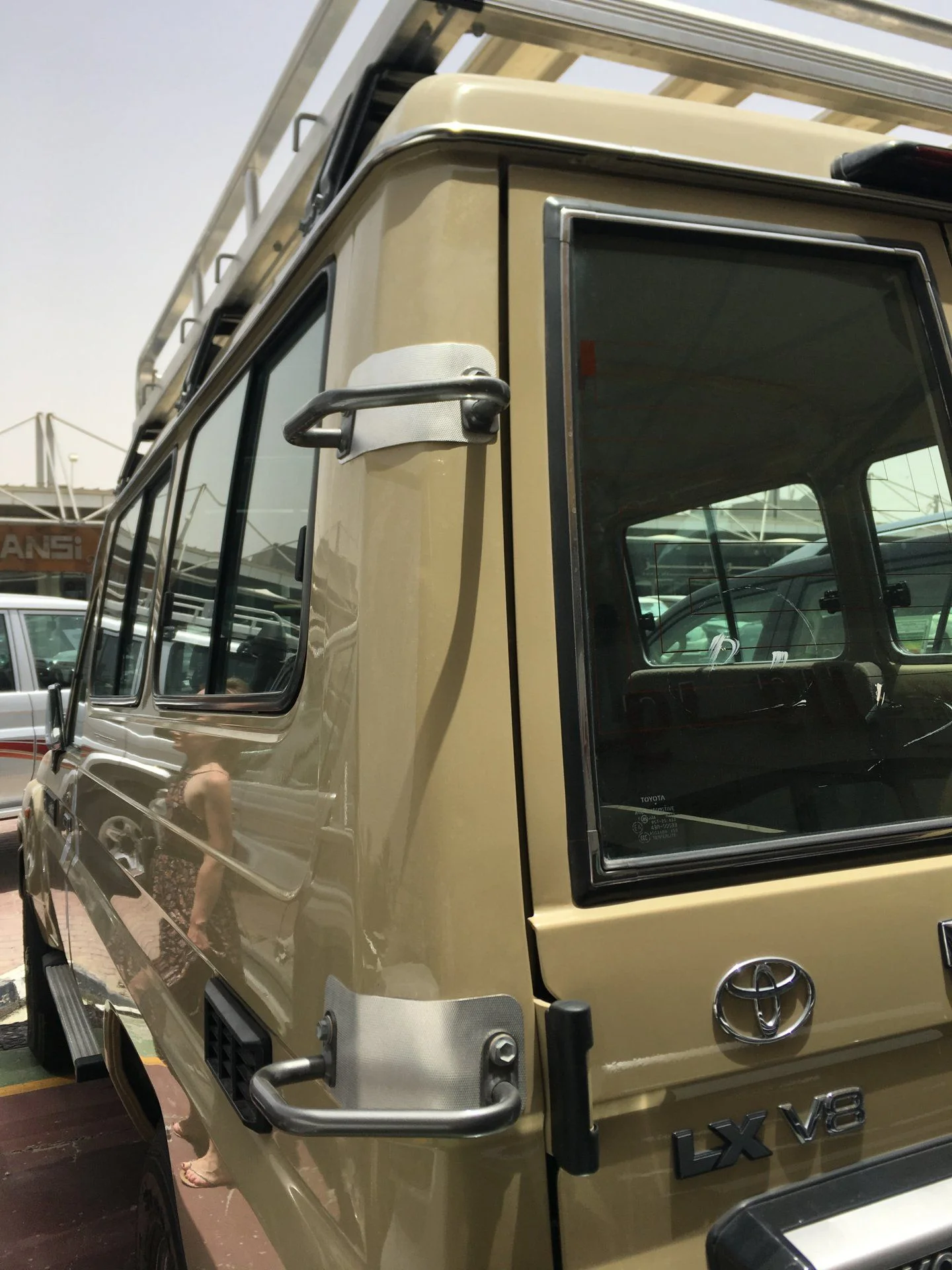
These turned up recently. Factory foot steps for the rear left pillar. Still waiting on one of the steps, but apart from installing these the plan will be to fab up similar steps for the rear right pillar and two on each side to keep the factory look going.

IMG_20180128_2326536.webp

IMG_20180128_2327117.webp

IMG_20180128_2328542.webp


Not sure if I'll install this thin aluminium shoe toe paint protector, as I would want to paint it and I'm not sure if I could source the same material so they all look the same. Had to order them to see what they were
IMG_20180128_2334031.webp
 
I also must put in some rele for fog lights , compressore , ecc .
From which amp would you recommend putting a rele ?
i know that for small amp , only fuse is required .
What is small ,or big ?

thanks Renago
 
I also must put in some rele for fog lights , compressore , ecc .
From which amp would you recommend putting a rele ?
i know that for small amp , only fuse is required .
What is small ,or big ?

thanks Renago
Hey Renago,
Amperage is rarely the main reason I use a relay, my attitude to using relays is as follows...
1. If the amps are bigger than what the switch is rated for, then you have no choice. But I would never run more than 25% of rated capacity through a switch, especially constantly.
2. If the relay box is near the battery, then a relay means no further live wires susceptible to damage and shorts when not in use, so I basically have anything exterior running from relays, regardless of amperage.
3. lots of bulky wires backwards and forwards through the firewall or any loom really gets hard to manage, so because none of my switches are near the battery, cranker or auxiliary, I prefer to use relays at the battery with 16awg on all switch wires (18 is hard to crimp well) and 16, 14 or 12awg on the power wires out of the relay straight to the device. I think it's easier, less wire and I think it's better for troubleshooting as the circuit is divided in two.

Not sure what compressor you have, most are +25 amps, but I'd guess you'd want a solenoid instead of a relay, same thing really but much higher amperage capacity. I also don't recommend putting more than 75% of rated load through a solenoid.
 
Last edited:
So here is the guts of the crank battery system. Edit: this has all changed now... see later on.

From the charger mainpost, there's a positive 2/0 cable that goes behind the dual fuse boxes and into the back of the 150 amp waterproof circuit breaker just above the charger, then back out to the positive terminal, the thinner of the two main terminal cables
IMG_20180206_2140464.jpg


This is as clean as I could get the battery terminals. The big positive 4/0 cable is all outgoing power, while the 4x fuse block is for stuff that must go on the terminal... volt and amp meter 10awg cables, as well as the AC charger cable and the solar charger 6awg cables. On the negative, there's a 4/0 from the block, another 4/0 going to the chassis, the dcdc charger fused negative, while the 4x terminal block also has the equivalent negative cables for the same meters and chargers mentioned on the terminal positive block.
IMG_20180206_2127291.jpg


The main positive 4/0 outgoing power cable runs to this pass through post, where the original loom is connected on the same side via the fusible links, whereas on the backside of the post and unseen is another 4/0 going to a 1000amp waterproof solenoid for the winch tucked in the same fender down near the bumper, two 2/0 cables going to each of the 100amp waterproof circuit breakers (then continueingto the fuse boxes) and another 2/0 that goes to a 500amp fuse that I'll get to next....
IMG_20180206_2133089.jpg
 
Last edited:
So here's the 500 amp fuse just in the fender behind the battery.
IMG_20180129_1036511.webp
IMG_20180129_1112534.webp


From there it runs more 2/0 to another 1000amp solenoid (in the fender behind the dual fuse boxes) for the starter motor shown below, and it also runs a second 2/0 to behind the drivers seat under the vehicle to another pass through post which will then go into the cab to a solenoid for the dual compressor and to the 500amp battery isolater I used to use in my dual system , that will only ever join both batteries or just the auxiliary directly to starter for an emergency start.
IMG_20180129_1109339.webp

IMG_20180129_1254039.webp
 
Last edited:
It was impossible to wire this without removing the door, you can only see the first looms and cable but it's chocker block full, but it's all ordered, fixed down and removable in parts if I have too
IMG_20180206_2128526.webp


Here's part of the cables running back underneath. There's a positive 4/0 from the alternator circuit post under the brake booster and a negative 4/0 from the chassis post near crank battery, both for the 240ahr auxiliary battery system and there's the 2/0 positive cable just mentioned above to join the batteries in an emergency. These three run to three pass through posts near the fuel tank and pop out behind the drivers seat where the auxiliary system will be mounted. The forth tube is four 6awg cables running from 4 more pass through posts underneath the back of the drivers seat on the door side that will go to the dual solar and dual AC chargers.
IMG_20180206_2132204.webp

IMG_20180206_2131458.webp

IMG_20180206_2130400.webp
 
These turned up recently. Factory foot steps for the rear left pillar. Still waiting on one of the steps, but apart from installing these the plan will be to fab up similar steps for the rear right pillar and two on each side to keep the factory look going.

View attachment 1627506
View attachment 1627509
View attachment 1627512

Not sure if I'll install this thin aluminium shoe toe paint protector, as I would want to paint it and I'm not sure if I could source the same material so they all look the same. Had to order them to see what they were
View attachment 1627514

Please post the picture with part number for the second step when it arrives ?

Awesome info as usual !
 
61058-90K03, arrived a few hours ago
View attachment 1629184

i have these in my shopping cart ready to have shipped from Japan. would you be willing to post some pics of yours installed? looks like they can go in several places along the back corner. curious where yours landed.
 
i have these in my shopping cart ready to have shipped from Japan. would you be willing to post some pics of yours installed? looks like they can go in several places along the back corner. curious where yours landed.
I'm still working on my double wheel/bicycle carrier which may or may not interfere with them in their intended position so unfortunately I'm not fitting them until after that's done.

That said, I've played around with them and the bottom one can go in one of two places, while the top one could also slide up and down a couple of inches and still work.
 
Did you fit the Aussie 180L Long ranger tank ?

I am in the process of acquiring one and would appreciate some feedback on your plumbing options etc as I think your model is(or rather used to be) about as basic as mine ?
 
Last edited:
i have these in my shopping cart ready to have shipped from Japan. would you be willing to post some pics of yours installed? looks like they can go in several places along the back corner. curious where yours landed.


Hi Paul, just posted a photo of the steps in factory position.,
 
Did you fit the Aussie 180L Long ranger tank
Nah, retro fitted the factory 90L tank and solenoid system. The rear filler was 'just' a matter of cutting holes and a bit of panelbeating and all the factory parts fit. Only difference is the spare-wheel type chassis which I modified to take the factory tank mounts.

The long ranger will be the easier option , you're just left with an ugly filler :)
 
Woulf love to see some pics of your aux tank solenoid system and wiring if you have some ? Did you match it to that OEM aux tank cluster on page 1 or 2 ?
 

Users who are viewing this thread

Back
Top Bottom