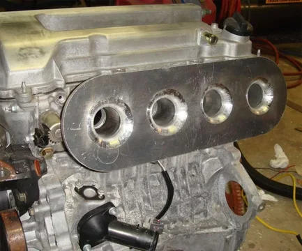
1HD-T Intake Manifold Modifications

This site may earn a commission from merchant affiliate
links, including eBay, Amazon, Skimlinks, and others.

to bad there is not enough room to extend the manifold past the last runner on the 1hdt,now that would be the ticket .

I think that a dual plenum design (pictured above) might help for filling that last cylinder as its purpose is to even out the intake flow to all the cylinders. The manifold for the 1hdt on the one side first has to feed cyl 4 then 5 and 6 lastly, so if the flow came from the side then it might get a more fair share. I wonder if you could cut and weld on a second plenum and just move the charge pipe over and block off the origional intake to the manifold for that. I think I remember reading that cyl 1 and 6 and are cheated out of proper flow and have shown piston damage from high egts. Perhaps some one could speak to that who onws one. I have often thought the 3B manifold design does cause cyl 1 and 4 to run rich, so I always asume my egts are higher from those cylinders than what my guage is reading.
 
Last edited:
my understanding or lack of ,is that the trick of a turbo and system design is to keep the charged air right at the entrance of the intake ,which is more forgiving with a center entrance vs a end entrance as the charge can move up and down your pipeing,and be further compounded with a tapperred entrance.for me the intake mod was more of a larger stored charge area needed for the higher rpm demand for air which is from more fuel period,thus this changes your whole air flow design turbo included .your one off turbo design for your larger intake is probably a great example even without the extra fuel or rpm demands of your new intakes full potential. again i am sure your turbo guy could touch on this before everyone goes out and enlarges thier manifolds
 
I think that a dual plenum design (pictured above) might help for filling that last cylinder as its purpose is to even out the intake flow to all the cylinders. The manifold for the 1hdt on the one side first has to feed cyl 4 then 5 and 6 lastly, so if the flow came from the side then it might get a more fair share. I wonder if you could cut and weld on a second plenum and just move the charge pipe over and block off the origional intake to the manifold for that. I think I remember reading that cyl 1 and 6 and are cheated out of proper flow and have shown piston damage from high egts. Perhaps some one could speak to that who onws one. I have often thought the 3B manifold design does cause cyl 1 and 4 to run rich, so I always asume my egts are higher from those cylinders than what my guage is reading.

That dual cylinder plenum picture is a terrible idea.
 
Greg, the reason for the bell-mouth is to stop what's called a "vena contracta" forming. Basically if you try to get fluid into a straight pipe from a large reservoir the fluid can't turn the sharp corners into the pipe and the flow contracts down to about 60% of the pipe area.
This doesn't restrict the flow by 60%, but it does make for bigger pressure losses and can be a real problem if you hit choke flow.

With a good bell-mouth you get smooth entry and flow across pretty much the full pipe diameter. Regarding tapers, I'm not sure, I've never done any work in that area. I've only used tapers as transitions, rather than working parts.
 
That dual cylinder plenum picture is a terrible idea.

Thanks Boy, but if you add some reason it might be more meaningful.
Thanks Doug for explaining that. From some flow models ive seen it looked like straight pipe has low pressure areas imediately around the inner edge of the pipe (eddies?), where as the flaired ones are stable across the whole diameter.
So would a simple flair transition on the floor of the manifold be enough, or is the full raised bell mouth such an improvement that it would be worthwhile? They look neat, but would be alot more difficult to fabricate. I do remember reading that air flow slows down and stagnates the closer it gets to a surface. Perhaps that is why they raise the trumpets. Would something like this be enough?
project06.webp
project06.webp
 
Thanks Doug for explaining that. From some flow models ive seen it looked like straight pipe has low pressure areas imediately around the inner edge of the pipe (eddies?), where as the flaired ones are stable across the whole diameter.
So would a simple flair transition on the floor of the manifold be enough, or is the full raised bell mouth such an improvement that it would be worthwhile? They look neat, but would be alot more difficult to fabricate. I do remember reading that air flow slows down and stagnates the closer it gets to a surface. Perhaps that is why they raise the trumpets. Would something like this be enough?

Yes, that's exactly it. You'll end up with eddies like a swirling donut in that area on a sharp edged pipe. Anything radiused like the picture you've shown will help. The bigger the radius, the smoother it'll be. I remember something like 1/6th of the pipe diameter is the mimimum radius to work effectively. Bell-mouths with their varying radius are better still, but much harder to make.

Most of the fluid work I do is with water which is incompressible and much easier to predict. Graeme may be able to help more with the compressible flow and pressure waves in air. But for turbo engines tuning based on pressure waves is almost impossible as the speed of the pressive waves changes with the air temperature. Which changes with boost.
 
"A Yanmar 6LP-DTP is a 1HD-T Base engine, all the same internals, but running a lot higher horsepower....

Anyone familiar with them?
 
I was sitting on one last week. It is a 4 valve btw.
 
unlimited supply of ice cold sea water in the aftercooler perhaps? Marine engines also run in a steady state more often than not. ie- you set it at a certain cruise RPM and leave it there. Marine propulsion engines are also rated at a horsepower duty cycle- so many minutes per hour at WOT etc... Highest rating would be 'Pleasureboat' and would have a very intermittent duty cycle whereas 'Workboat' would have a lower rating and more allowable time at high load factor. The 6LP Yanmar is most certainly at the 'Pleasureboat' end of the rating at this horsepower. Incidentally- it is 315 hp at the crank at 3800 rpm...

Oh yeah- the turbo can be optimized for on boost performance rather than quick spool too....

think of it this way

6-71 Detroit Diesel 426 cubic inch naturally aspirated 310 HP < 10,000 hours
same engine turbo intercooled bypass 485-525 HP >2000 hours then POP!
 
Last edited:
What do you figure makes them so different in terms of horsepower???

As Sailor said, lots of intercooling, but also a bigger turbo than you can run on a land vehicle. Low end torque isn't such a priority on a boat as it is in a 4wd.
 
Well that depends on the boat! lol!

Here is the size of turbo I usually deal with and there are 2 of them on this engine. (from another thread) My turbo diesel knowledge is based on marine experience, I am happy to pass the vehicle expert laurels to you guys here...

BTW the only boat I would have a 4.2 Toyota based prime mover in would be very light ,fast and easily driven...
IMG_0238.webp
 

Any updates on the pie warmer yet :)
Have you got it running yet ?
Been on the dyno ?
What's the numbers (Kw,torque,boost,egt)

How do you get all of the air out of the system with the filler in that position?
How about some pics of the heat exchanger?

Hamo
 
It's still in testing stage with some very interesting results so far. No water has been in the cooler yet as I'm testing the turbo and plenum. All in good time.

You can call it a pie warmer but it runs alot lower intake temps than your front mount. ;).
 
top mount runs cooler than a front mount,wow shows you how much i know. sounds like someones hungry and is not going to get his piece of the pie. bottom line question is ,so im getting that your saying that after we all enlarge our intake like yours that we could run any of your bad boy turbos without flow ,surge issues (i think not), or does everything change in turbo design when you alter your manifold (especially with a large front mount inter cooler). Or quite simply have you just maxxed out what you can squeeese out of a ct26 , even before you start moding the fuel to match. might be better off leaveing the manifold as is ,just to simplify universal turbo design . ha ya right. good to see a engineer is finally designing a larger intake . just to bad it was not with the superior front mount cooler . but i am sure volume has alot to do with it.
 
Last edited:
sounds like someones hungry and is not going to get his piece of the pie. bottom line question is ,so im getting that your saying that after we all enlarge our intake like yours that we could run any of your bad boy turbos without flow ,surge issues, or does everything change in turbo design when you alter your manifold . Or quite simply have you just maxxed out what you can squeeese out of a ct26 , even before you start moding the fuel to match. might be better off leaveing the manifold as is just to simplify established turbo design . ha ya right.

Who are you addressing this post to?
 
I think if you were dealing with potential surge with a turbo at low rpm, building a manifold to increase VE would only serve to lessen the surge. To what degree I dont kow, but it certainly wouldn't make it worse. That is unless the manifold screwed with the low rpm VE which would suck
I would be interested to see the air/water cooler post temps after 1 min of sustained boost after the coolant stabilizes. My top mount is air/air and with a 4 inch core it take a while before it heat soaks and gives me a reliable reading.
 
It all comes back to whats better, ATA vs WTA. Front mounts have a 65% efficency rating. Say 150 intake temp. 30' ambient. 150 - 30= 120 x .65= 78' intake temp. Safari says it cuts it by 50%. 150/2= 75'.

WTA starts at ambient and depending on water volume as to how long before heat sink accures. The heat value transfer rate from air to water (no matter if its hot or cold) is the same. So if your intercooler holds 1 litre volume of water and your heat exchanger holds 1 litre of water. The transfer rate is the same. Meaning at heat soak 150 degrees hits the water. Ambient 30 degrees then hits it at the heat exchanger. 150-30=120. 120/2=60' + ambient = 90'. So it's a big 12 degrees more than ATA. To get past the volume of air 2 bar. You just run a heat exchanger with twice the surface area.

So what's the problem? Water boils at 100 degree's. adding a glycol component reduces the water efficency to 90%. With a Constant source of cooling (refrigeration system) it will be very easy to maintain below ambient temps. Running a slower flow rate pump in the refridge heat exchanger and other variables with also help. The pull down on a ac compressor is huge and can handle it just fine. The loss of power running the compressor is null and void because your putting it back into the engine (dropping the intake temps by 30' alone will almost cover what the compressor uses without any other mods). It's also self regulating. Meaning the harder you rev, the more it cools which is perfect. But I have ALOT more testing to do yet.
 

Users who are viewing this thread

Back
Top Bottom