Navigation
Install the app
How to install the app on iOS
Follow along with the video below to see how to install our site as a web app on your home screen.
Note: This feature may not be available in some browsers.
More options
Style variation
You are using an out of date browser. It may not display this or other websites correctly.
You should upgrade or use an alternative browser.
You should upgrade or use an alternative browser.
1978 LPB Teardown and Rebuild (2 Viewers)
- Thread starter Awl_TEQ
- Start date
This site may earn a commission from merchant affiliate
links, including eBay, Amazon, Skimlinks, and others.
More options
Who Replied?Awl_TEQ
Supporting Vendor
- Thread starter
- #222
Kevin,
I hope you are planning to sell those motor mounts- they are beautiful!
Cheers,
Josh
Yup - I have a customer who wanted some so mine were the first article. They are a real PITA to bend. Because of the shape I can't use a backstop and therefore have to align the part to the tool by eye. Any missalignment causes the two mounting flanges not to be in the same plane = scrap metal.
Kevin
- Joined
- Sep 28, 2002
- Threads
- 558
- Messages
- 8,122
- Location
- Kamloops, BC Canada
- Website
- www.shopraddcruisers.ca
Thanks Rob,
I'm just using them for the battery brackets so I guess they'll be ok. The motor frame brackets will be bolted with fine thread and tack welded in the corners.
Kevin
No problem Kevin, I never would of tried it if Kurt from Cruiser Outfitters said he has used them on many installs if memorey serves me.
Really like those brackets, top notch.
Rob
- Joined
- Sep 28, 2002
- Threads
- 558
- Messages
- 8,122
- Location
- Kamloops, BC Canada
- Website
- www.shopraddcruisers.ca
I went on a little road trip yesterday and scored some new to me side steps for the 45. 3_puppies gave me a generous deal on these - thanks Paul
View attachment 354903
View attachment 354904
Kevin, it was good to meet you the other day and glad you made it home.
Paul
whitey45
SILVER Star
Kevin, are you planning on installing the engine trans with a factory "cant" I think it is 7 degrees, I never even knew toyota did this until I got the bj60. It is very noticable when the shroud is removed. Also wondering if anybody knows why this was done? When I swap this engine into my 45 I will want to install it like every other engine install,centered up or off set a little! ..Or I will install it the same way toyota did it utilizing the factory mounts...
Awl_TEQ
Supporting Vendor
- Thread starter
- #231
Whitey
Short answer is yes
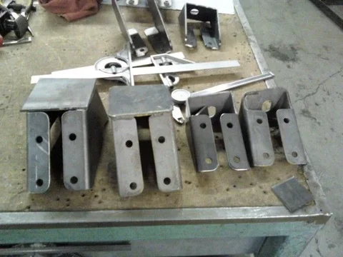
I am using replica (I made them) factory frame brackets and motor mounts in the factory positions... so the motor will tilt to the side and back as per the original 40 series design. I have reproduced the brackets using an original set as a template and will do a run of these parts in the next few weeks as time allows.
Flat layout

formed up
I have no idea why they tilted the motor - ours is not to reason why... ours is but to refurbish and enjoy


Short answer is yes
I am using replica (I made them) factory frame brackets and motor mounts in the factory positions... so the motor will tilt to the side and back as per the original 40 series design. I have reproduced the brackets using an original set as a template and will do a run of these parts in the next few weeks as time allows.
Flat layout

formed up

I have no idea why they tilted the motor - ours is not to reason why... ours is but to refurbish and enjoy
Last edited:
whitey45
SILVER Star
That works for me,I am not too concerned about the tilt angle thing,just curious as to the engineering behind it. I am going to harvest every last piece off of the 60 to ease the transplant,I wish I didnt have the frame mounts after seeing ANOTHER amazing reproduction.
Awl_TEQ
Supporting Vendor
- Thread starter
- #233
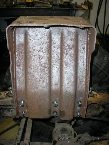
I took a bit of time tonight to install the M8 nutserts (captured nuts) in the frame for the battery brackets. I still don't like these things for a few reasons. One is that the nutsert only threads onto the tool by a about three threads and the force necessary to expand and seat the nut can sometimes pull and strip the nutsert. I have had that happen on many different sized nuserts. Other than being very careful with how much force and how straight you pull I have found if you start the seating process and then slack off to thread the nut on a bit more you can then pull it all the way in. Another reason I don't like them is I find they don't hold up to very much torque before they spin and become useless.
Having said all that I really have no other choice besides cutting open the frame and welding in nuts. There is just no access to hold a fastener in there. So here are some shots and comments.
The tool:
The nutsert threads onto the tool while holding the tool open. Then when squeezed the nutsert expands and becomes captured in place.
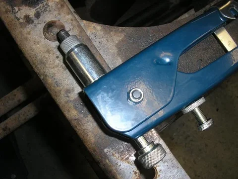
This particular tool is slightly small for this size nutsert but with only 13 to instal I wasn't willing to buy the $150.00 big one. Rather than strain all the ligaments in my wrists and forearms I added a little leverage to the tool in the form of some aluminum tubing.
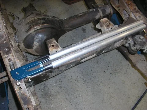
Here is an unseated nutsert


Having said all that I really have no other choice besides cutting open the frame and welding in nuts. There is just no access to hold a fastener in there. So here are some shots and comments.
The tool:
The nutsert threads onto the tool while holding the tool open. Then when squeezed the nutsert expands and becomes captured in place.

This particular tool is slightly small for this size nutsert but with only 13 to instal I wasn't willing to buy the $150.00 big one. Rather than strain all the ligaments in my wrists and forearms I added a little leverage to the tool in the form of some aluminum tubing.

Here is an unseated nutsert

Awl_TEQ
Supporting Vendor
- Thread starter
- #234
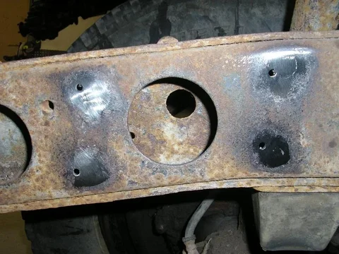
I installed the right side. It looks a bit swiss cheesy here but its not too bad in person.

The left side has some conflicts with the existing 2F mount rivet holes. The larger holes shown here are from the 2F mounting brackets that I removed. The smaller ones are pilot holes for the nutserts that need to be drilled out to a touch over 1/2". With them so close together drilling would be a PITA and the nutsert won't anchor properly. So I will weld the offending holes shut.
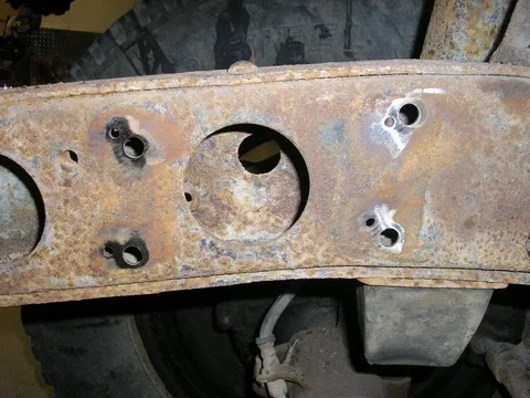
I want a smooth inner surface after I am done so I clamped a bit of 1/2" thick aluminum to the inside of the frame. When I MIG the hole shut the filler material will not adhere to the aluminum and it is much easier to fill the holes. In this shot I have already done the lower hole and am prepared to do the upper one.


The left side has some conflicts with the existing 2F mount rivet holes. The larger holes shown here are from the 2F mounting brackets that I removed. The smaller ones are pilot holes for the nutserts that need to be drilled out to a touch over 1/2". With them so close together drilling would be a PITA and the nutsert won't anchor properly. So I will weld the offending holes shut.

I want a smooth inner surface after I am done so I clamped a bit of 1/2" thick aluminum to the inside of the frame. When I MIG the hole shut the filler material will not adhere to the aluminum and it is much easier to fill the holes. In this shot I have already done the lower hole and am prepared to do the upper one.

Awl_TEQ
Supporting Vendor
- Thread starter
- #237
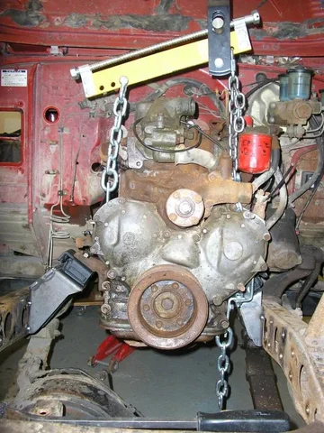
So I used the chassis manual and photos from several builds both on mud and elsewhere to locate the engine frame brackets. I also used threads by Otterav and DanS HJ-45 - thanks guys. I tack welded them in place for now while I mock up the motor, exhaust, turbo, power steering, alternator, York compressor, A/C compressor, dual batteries, rad, condenser, intercooler and front clip (whew!) Yeah, I know, I don't think its all going to fit either .
.
Some comments on "slipping" the drive train in.
Not so much slipping as bouncing, banging, prying... I know! shouldn't be that tough, and it wasn't really. I just had to re-rig my lifting rig half way through because my leveler was hitting the hood/ firewall. Plus with the weight of the tranny/case it was hard to get it to line up with the engine brackets. So with a floor jack under the t-case and the leveler running sideways it was much better.
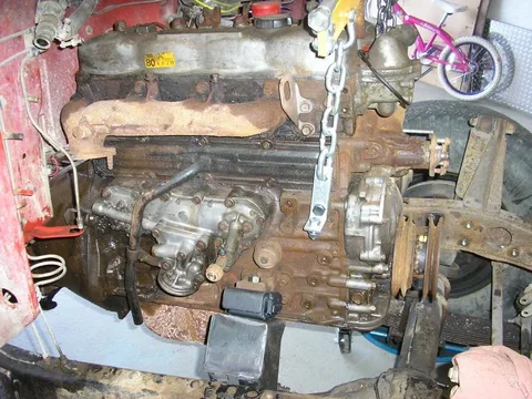


 .
.Some comments on "slipping" the drive train in.
Not so much slipping as bouncing, banging, prying... I know! shouldn't be that tough, and it wasn't really. I just had to re-rig my lifting rig half way through because my leveler was hitting the hood/ firewall. Plus with the weight of the tranny/case it was hard to get it to line up with the engine brackets. So with a floor jack under the t-case and the leveler running sideways it was much better.


Awl_TEQ
Supporting Vendor
- Thread starter
- #238
One more - holy offset batman
This is what I hope to end up with plus a York OBA compressor (and prettier intercooler tubing) This shot is from Hilltop Cruisers website and is the truck in my member page background. Obviously I am just doing mockup right now - I got a long way to go...
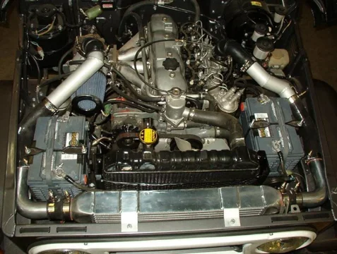


This is what I hope to end up with plus a York OBA compressor (and prettier intercooler tubing) This shot is from Hilltop Cruisers website and is the truck in my member page background. Obviously I am just doing mockup right now - I got a long way to go...

Awl_TEQ
Supporting Vendor
- Thread starter
- #239
Okay, the motor brackets worked the tranny is in the right place (this is a forward tower h55f from a BJ42)

Two issues have cropped up.
Firstly, the crossmember is too wide. A quick look in the FSM shows the BJ42 frame is the same width at the front but tapers wider sooner than the FJ45 frame. The BJ42 frame begins to widen just aft of the spring hanger - the FJ45 frame starts to get wider after the front body mount. Net effect is the crossmember is 1" - 1.5" too wide. This is easily fix by moving the holes in the L-brackets at the ends of the crossmember.
Here you can see with the crossmember where it needs to be the captured nut doesn't line up with the hole in the L-bracket.
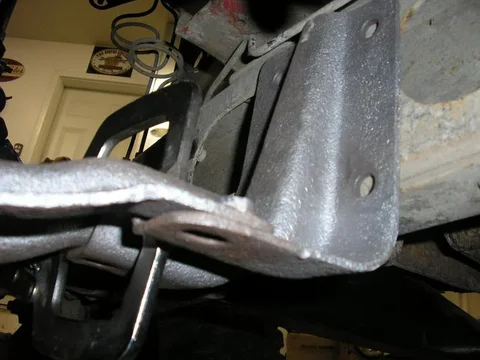
The second issue is a bit more trouble and I'd love to hear from anyone with this situation in their rear view mirror. With the motor mounts correctly positioned and the tranny/ t-case pushed up until contact is made with the doghouse this is where the L-brackets land on the frame. Too low to use the holes as is.


Two issues have cropped up.
Firstly, the crossmember is too wide. A quick look in the FSM shows the BJ42 frame is the same width at the front but tapers wider sooner than the FJ45 frame. The BJ42 frame begins to widen just aft of the spring hanger - the FJ45 frame starts to get wider after the front body mount. Net effect is the crossmember is 1" - 1.5" too wide. This is easily fix by moving the holes in the L-brackets at the ends of the crossmember.
Here you can see with the crossmember where it needs to be the captured nut doesn't line up with the hole in the L-bracket.

The second issue is a bit more trouble and I'd love to hear from anyone with this situation in their rear view mirror. With the motor mounts correctly positioned and the tranny/ t-case pushed up until contact is made with the doghouse this is where the L-brackets land on the frame. Too low to use the holes as is.

Awl_TEQ
Supporting Vendor
- Thread starter
- #240
With a call in to a friend who has put a few 3B's into FJ frames I still have no answer. Is this a part issue - ie. wrong crossmember? (I removed this x-member from the BJ-42 frame myself though I did not pull the drive train).
Or does the stock 42 doghouse have more height?? (I doubt it)
Here are some more shots with my member ( ) positioned where it wants to go.
Holes too low
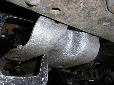
Member and t-case hang low - member= 2.5" and case= 4.5" below the frame


Again - the tranny is near touching the doghouse. Should I weld shut the useless holes and drill new ones??
Everyone I have heard says the BJ42 series drive train will fit right into an FJ40 but what about a 45 - anybody actually done one??


Or does the stock 42 doghouse have more height?? (I doubt it)
Here are some more shots with my member (
Holes too low

Member and t-case hang low - member= 2.5" and case= 4.5" below the frame


Again - the tranny is near touching the doghouse. Should I weld shut the useless holes and drill new ones??
Everyone I have heard says the BJ42 series drive train will fit right into an FJ40 but what about a 45 - anybody actually done one??
Similar threads
Users who are viewing this thread
Total: 3 (members: 0, guests: 3)


