Which plugs should I be running - B, 2B, 3B, H and 2H diesels (2 Viewers)

This site may earn a commission from merchant affiliate
links, including eBay, Amazon, Skimlinks, and others.

So I have Superglow apparently. (1985 HJ60)
Going off the volt meter, I think they glow at 6 volts for about 2 seconds, and then after glow for a bit longer, the time depending on the temperature, at 3 volts think. Is that correct?

.....I would have expected to see double those voltage readings ... but then I'm unfamiliar with Super Glow.
At this stage I would have expected around 12V being applied in the first stage and then around 6V for the second stage. But I intend to research better answers for this further down the thread when I'll look at wiring diagrams for each type of pre-heating system.....

Well. - At this point in time I still suspect you should see 12V in stage one followed by 6V in stage 2.

What voltage figures do other owners of 12 volt HJ60 Super Glow cruisers see?

If your low figures aren't normal (as I suspect), perhaps they're cause by
  • a weak battery
  • damaged contacts inside your glow relays
  • a weakened (high resistance) fusible link feeding your plugs
  • a poor connection somewhere in your busbar feed wiring
(Assuming your voltage measurements were obtained accurately of course.)

:cheers:

Edit: Here's another couple of Super Glow pre-heat diagrams that I've just uplifted from another thread:

AnotherFSMimage.jpg

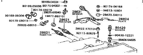
I note that they too show the mysterious "Sensing Resistor" aka "Glow Plug Current Sensor". What does this thing look like? (If they really do exist and anybody has one.)

At first I thought it was the thing that commonly appears on the intake manifold of cruisers with Super Glow (that outwardly resembles a glow plug).

But this image squashed that idea:

TestingGlowPlugResistor.jpg

Apparantly that one is the "Glow Plug Resistor" (aka "Dropping Resistor") which drops the voltage to the plugs for the 2nd stage of pre-heat.

I eagerly await enlightenment :frown:

Edit. :clap::clap: Rudi just came to my rescue with another Email message. Here's what I've been looking for on a 2H engine in an HJ75.

GlowPlugCurrentSensorHJ75.jpg

It is a little bent-up strip of flat metal (with sensor wires attached) that carries all the juice to the glow plug busbar. (So it must indeed provide current-flow feedback to the "timer" by sensing voltage-drop along its length.)
AnotherFSMimage.jpg
TestingGlowPlugResistor.jpg
GlowPlugCurrentSensorHJ75.jpg
 
Last edited:
Getting to understand Super Glow (I'm making progress but still have a way to go.)
Clearly (judging from the different diagrams I've posted already) there are a number of different versions of Super Glow in use with our IDI diesels.

The brains behind it all is a "black box" upon which Toyota bestows (in a massive understatement) the simple name - "Timer".

And the use of this "timer" is a significant move away from the simplicity that is synonomous with the magnificent 40-series. (Ignoring the EDIC system which is a little complex too - But at least if this fails, you simply unclip and remove the arm between the injector pump and the EDIC motor to get mobile again in an instant.)

In the wiring diagrams I've posted of this preheat system, you can see that this "timer" can
  • know when you're cranking (because it is connected to the ST terminal on the key-switch)
  • know when your engine starts running (because it is connected to the alternator "L" (lamp terminal)
  • know how much current the plugs are drawing (because of its wires to the "Current Sensor")
  • etc
Yet why does it need to know all this? What does it actually do as a result of this information? Because despite all the complexity of the "timer", these diagrams I've posted all show just 2 stages/steps of preheat.

The first stage connects the glow plug busbar directly to the battery for a brief period. Whereas the second stage (which is better called "After Glow") drops the voltage via the "dropping resistor" (aka "glow plug resistor").

Here are some graphs associated with the bottom diagram I put in post #40. If we can understand these then perhaps it will shed some light on it all? :hmm:

Graphs.jpg

I can understand only the RH graphs at this stage.

For the 12V version I've drawn a red line showing that with a 25 oC coolant temperature you can expect the glow light to illuminate for just 2.8 seconds before you're ready to crank. (But does this mean the 1st stage of pre-heat lasts only 2.8 seconds too? I'm unsure!)

And with a green line I've shown that with a 20 oC coolant temperature you can expect your "After Glow" to continue for about 48 seconds.

Now can someone explain the graph on the left? I'm stumped at the moment!

:beer:
Graphs.jpg
 
Last edited:
Well. - At this point in time I still suspect you should see 12V in stage one followed by 6V in stage 2.

What voltage figures do other owners of 12 volt HJ60 Super Glow cruisers see?

If your low figures aren't normal (as I suspect), perhaps they're cause by
  • a weak battery
  • damaged contacts inside your glow relays
  • a weakened (high resistance) fusible link feeding your plugs
  • a poor connection somewhere in your busbar feed wiring
(Assuming your voltage measurements were obtained accurately of course.)

:cheers:

...

That is indeed entirely possible. My HJ60 had lots of electrical problems when I first bought it. And the glow plug circuit had 3 seperate faults in it at some point.

I'm just going off what the dashboard volt meter says. I think it's accurate, because it reads 12 volts when the engine is off, and 14 when driving. And about 13 when idling.

Battery is quite new, so it must be one of the other options left.

Especially in winter, the engine always starts up at the first attempt, but very roughly.

But with a bit of help from the info on this thread, I may be able to figure it out. And figure out Superglow.
 
My theory

Getting to understand Super Glow ........................

Now can someone explain the graph on the left? I'm stumped at the moment!

:beer:

Here is MY theory: first of all I think an important line is missing in the graph. See the red line in the graph below.
graph pre heat edited.JPG
Now read the graph from right to left and it start making sense.
The first 12 seconds is 12 Volt, after that the voltage drops from 12V to +/- 9Volts after 19 seconds on the glow plug terminal bar.
Why? I think the Glow Plug Resistor acts in the same way as the old glow controller. The resistor gets hot, the R value goes up, the I (amps) goes down so the U (volts) goes up over the resistor, which means the U (volts) goes down over the glow plugs (= Glow Plug Terminal Voltage).
glow plug terminal voltage.jpg
Having said this; I think the No.2 relay is the pre heating/glow relay and the No.1 relay is the after glow relay.

I'm open for discussion(s)

Rudi
graph pre heat edited.JPG
glow plug terminal voltage.jpg
 
....I'm just going off what the dashboard volt meter says. I think it's accurate, because it reads 12 volts when the engine is off, and 14 when driving. And about 13 when idling. ...

Your battery and charging system both sound OK Vince. Besides, when a battery is weak (or too small etc), this normally shows up as "very slow cranking" or "a chattering starter-solenoid" while you're attempting to crank ..... and you haven't mentioned any of that.

By the way, to gather busbar voltage readings, you needed to have someone go through the normal starting procedure with the key while you're under the bonnet/hood with a multimeter (set to the appropriate DC voltage scale) and with the -Ve lead clipped-to bare metal on the engine while the +Ve lead touches bare metal on the busbar that runs between the glow plugs. I presume you got your busbar readings ("6V dropping to 3V") this way.

I wonder if someone else with Super Glow could do this for us and report back with their vehicle's model and build year together with information on how they saw their busbar voltage readings vary?

Here is MY theory: first of all I think an important line is missing in the graph. See the red line in the graph below.
View attachment 513259
Now read the graph from right to left and it start making sense.
The first 12 seconds is 12 Volt, after that the voltage drops from 12V to +/- 9Volts after 19 seconds on the glow plug terminal bar.
Why? I think the Glow Plug Resistor acts in the same way as the old glow controller. The resistor gets hot, the R value goes up, the I (amps) goes down so the U (volts) goes up over the resistor, which means the U (volts) goes down over the glow plugs (= Glow Plug Terminal Voltage).
View attachment 513260
Having said this; I think the No.2 relay is the pre heating/glow relay and the No.1 relay is the after glow relay.

I'm open for discussion(s)

Rudi

Good theory Rudi!

But 12 seconds sounds too long to me to be hitting 6V plugs with 12 volts (which is TWICE their nominal voltage). And the pre-heat light would have extinguished after roughly 2 seconds telling the driver to crank away. So why would our intelligent black box (err.... "timer") leave the first stage on for a further 10 seconds if 2 seconds was sufficient to achieve "spontaneous combustion of the atomized diesel on compression"? This doesn't make sense!

I must have sat down in front of the gas heater for hours last night staring at that damned graph. (Perhaps if I do the same again tonight the answer will come to me?)

:beer:

So here are the $64.000.000 questions:
What happens between 0 and 10 seconds?
Calculating time for the Timer?
Since when starts a graph in mid air?
Which relay is doing what?

Relay No.1 has no control device to regulate the current or the voltage other then the timer. So the 6V plugs are getting 12V for a ??? seconds.
Relay No.2 has the Glow Plug Resistor in series, which means there is a "form" of control to regulate the current / voltage.
I stick to my opinion that the (heat depending) Resistor (NTC or PTC ? can't remember, it's too long ago) takes care of not overheating the 6V glow plugs. Also here the timer is responsible for the ??? seconds.

On the RH graph I think the red and green lines are pointing the wrong way. The green one must point to the left and the red one to the right and then the readings are;
Light Lighting Time at 20`C = 3.2 seconds
After Glow Time at 25`C = 40 seconds.
These numbers I can live with. But only if the 3.2 seconds comes from the No.1 relay and the 40 seconds afterglow from the No.2 relay.

That leads me to the conclusion that the Super Glow system is mis-using or abusing the 6V glow plugs by using a timer as a control device.

I see no possibility that the glow plugs are getting 6V or less.
I only see 12V and less.
The solution is to ask a superglow owner to do some measurements ad describing the sequence of what is happening.

Something else is bubbling in my gray stuff but is doesn't come up at the moment. Maybe later.

That's it for now,

Rudi

P.S. This posting of mine may have spelling errors in it since English is NOT my first (or second) language. Unfortunately the edit function is gone so you guys have to live with it.
 
...On the RH graph I think the red and green lines are pointing the wrong way. The green one must point to the left and the red one to the right and then the readings are;
Light Lighting Time at 20`C = 3.2 seconds
After Glow Time at 25`C = 40 seconds.

Thanks for pointing out my mistake Rudi.

I've corrected the lines now (and corrected the values I took from them) ........ but in a different way to how you suggested.

With the way I've done it, the lines now represent:
Light lighting time at 25 oC coolant temperature = 2.8 secs
After Glow time at 20 oC coolant temperature = 48 seconds

(Doing it differently wasn't intentional - As soon as I saw your comment and realised my mistake I rushed in and changed it all without reading any further. :eek:)

...These numbers I can live with. But only if the 3.2 seconds comes from the No.1 relay and the 40 seconds afterglow from the No.2 relay.....

Yes. I expected it to work like that. But then I'd have expected Toyota to say "Preheat Duration" instead of "Light Lighting Time" (or at least to have the decency to explain that the light illumination period mimics the 1st heating stage.)

And those LH graphs are still "throwing me".

:beer:
 
It is a little bent-up strip of flat metal (with sensor wires attached) that carries all the juice to the glow plug busbar. (So it must indeed provide current-flow feedback to the "timer" by sensing voltage-drop along its length.)

FYI, the little bent-up strip of flat metal from your picture is not part of the Current Sensor. My current sensor is currently dead which I think is one source of all my electrical problem...

Nice post BTW :popcorn:
 
FYI, the little bent-up strip of flat metal from your picture is not part of the Current Sensor. ... :popcorn:

Can you please explain further Biche? (Perhaps with a photo.)

Toyota themselves actually label that bent strip as the sensor and I can see the wires and connector attached to it in the image I've posted :frown:

GlowPlugCurrentSensorEPC.jpg

It looks different in different models though. (I just posted the HJ75 image because the sensor seemed to be clearest there.)


:beer:
GlowPlugCurrentSensorEPC.jpg
 
Last edited:
Righty ho. I've read a lot of threads on "Super Glow woes" and come to the conclusion that the system is widely misunderstood and not as bad as many people think.

I'll take a stab at how I think Super Glow works...(taking a 12V BJ60 as an example):


  • When you turn your key to "on", the pre-heat light illuminates according to the graph in post #42 and the "timer" automatically connects your busbar directly to your battery via No. 1 relay.
  • You can choose to crank as soon as the light is extinguished (like Toyota aimed for you to do), and if you do that (and if your engine starts as a result), the "timer" automatically de-energises No. 1 relay to stop pre-heat.
  • However you may choose to ignore the light and continue waiting. In this event, the "timer" will automatically "chop out" No. 1 relay a second or two later. Many people apparently prefer this extra wait and listen for the sound of No. 1 relay re-opening while watching to see their voltmeter needle jerk back up slightly. (Both these things verify that No. 1 relay has opened). Cranking at this later time is apparently more likely to result in a "clean" start - under very-cold conditions, or if your cylinder compression figures are down, etc.
  • Once the engine is running, the "timer" automatically energises No. 2 relay to apply "After Glow" which continues automatically for the period shown on the RH graph. And during "After Glow" the busbar voltage is reduced by the Glow Plug Resistor (to somewhere close to the plug's nominal voltage specification).
So how do I explain those peculiar graphs on the left in post #42? Answer: "I can't - Other than by suggesting they are just another example of mistakes being made by Toyota when "cutting and pasting" information between their various FSMs."

So what voltage should appear at the busbar? Well I suggest for this 12V BJ60 you should aim to see 12V during Pre-heat and 6V during After Glow.

But when I look at all the threads from people who have "Super Glow Woes" ..... I see them usually measuring less than this. (Typically 8.5V for Pre-heat and 4.5V for After Glow.)
And I suspect here-in lies many of their problems! I suspect many should have concentrated on fixing this "weak voltage issue" rather than pointing the blame at the "timer" or at the "Super Glow system" as a whole.

Going off ALL the Super Glow wiring diagrams I've researched, weak busbar voltage figures can only arise from things like:
  • battery charge low
  • weakened/corroded fusible link
  • damaged relay contacts (No.1 or No.2)
  • loose or corroded terminal connections
  • weakened/corroded interconnecting wiring
:cheers:

Edit: While I think a 12V Super Glow system should ideally show busbar voltages of "12V pre-heat" and "6V after glow" (and the corresponding 24V system should ideally show "24V pre-heat" and "14V after glow") I think achieving this is "unrealistic". I suspect Toyota didn't quite size the wiring and relays (in the feed to the busbar) big enough to achieve this. (In other words - I suspect they "economised".) So I'd probably be happy enough to see figures like 10.5/5 for a 12V version and "23/13 for a 24V version.
But I'd love to see more feedback in this thread on what owners measure in reality.
 
Last edited:
Can you please explain further Biche? (Perhaps with a photo.)

Toyota themselves actually label that bent strip as the sensor and I can see the wires and connector attached to it in the image I've posted :frown:

It looks different in different models though. (I just posted the HJ75 image because the sensor seemed to be clearest there.)


:beer:
I'll get mixed based on a parts list that I have, but based on the diagram below, the plate doesn't belong with the sensor, which looks have is own.

CurrentSensor.png


I'm going to get a new one, I'll take a picture when I'll bring it home.
 
Rudi has been busy researching Glow Controllers and here are the results of his efforts:

GlowControllerSpreadsheet.jpg

:clap:
GlowControllerSpreadsheet.jpg
 
I've been looking at other catalogs and noticed an alarming trend where some manufacturers are choosing not to show vehicle model numbers at all. (Instead they simply show the engines.)

Here's an example of this from NGK (who incidentally don't appear to make any 6V or 23V plugs for our IDI cruisers at this point in time):

NGKexample.jpg

Such a catalog would probably make it hard for a customer to complain they were misled. (Is this their aim I wonder?) One thing for certain, it is rather a useless catalog for helping guide any customer who needs guidance! (Ignoring the miniscule number of landcruiser engines that are even mentioned there.)

These are the only NGK plugs that I can find right now that appear to be made for our cruisers:
Y-128T 8.5V 9A
Y-147T 10.5V 7A
Y-178T 20.5V 4.5A
Y-197R 14A 5A

And here is the NGK code breaker:

GlowPlugNGKcode.jpg

:cheers:

Edit: But we do appear to have a problem with the NGK Y-128T plugs! My equivalent HKT-brand plugs (PT104) draw 11A each (according to that manufacturer). So if I swapped to NGK plugs my pre-heat current should drop from 44A to 36A which is an 18% reduction. How could I possibly expect my glow controller to glow properly?
NGKexample.jpg
GlowPlugNGKcode.jpg
 
Last edited:
The problem of some new glow plugs being incompatible with Glow Controllers

This issue has been around for some time now.

When owners first began finding that their Glow Controllers wouldn't glow properly with the new plugs they'd purchased, I was convinced it was simply an "installation problem" (with perhaps the owners failing to ensure each and every plug was making proper electrical contact with its busbar). Then, the dedication and expertise of some owners led me to become suspicious of the virtues of the plug manufacturers themselves.

And while constructing this thread, my helpers uncovered concrete evidence of plug manufacturers having "lost sight" of the critical importance of "glow plug current draw" when Glow Controller preheat is being used. I'll give an example of this evidence here:

This is from an HKT catalog copied off the Internet right now (from an on-sellers website):

HKTcurrentPT104.jpg

And this is from an NGK catalog copied right now too:

NGKcurrentY128T.jpg

Both plugs are marketed for my own vehicle yet one apparently has a current draw specification of 9 amperes and the other - 11 amperes! So in my vehicle, a set of those HKT plugs would theoretically draw 44A (through my Controller) whereas a set of the NGK plugs would draw just 36A. (The situation for a 2H engine would be even worse: 66A versus 54A.)

Clearly the HKT set would be MUCH more likely to make my Controller glow properly - based on the plug manufacturers' own data. (And I'm grateful to those catalogs for at least showing us the current-draws because most others leave this VITAL specification out.)

I've now placed a Warning in post #1 of this thread about this important issue.

Unfortunately the only advice I can offer to owners of cruisers with Glow Controller pre-heat right now is to either
  • do "current draw research" yourself before purchasing, or
  • seek some form of guarantee from the seller that the plugs you are about to buy will indeed operate your controller properly. (And in reality you may only be able to go off your judgement of the seller's experience ... because I think "technicalities" will make it hard for anyone -even honest sellers - to offer refunds/exchanges.)
PS. For the convenience of readers, I've relisted the "Glow Controller plugs" from post #1 alphabetically here:

12V cruiser (8.5V plug)

  • APS 5013
  • Bosch GPT208
  • Champion CH121
  • EIKO GT208
  • HKT PT104
  • JKT PT104
  • ND 067100-1350
  • NGK Y-128T
  • MAY PT104
  • Toyota 19850-68030
  • VSP PT104


24V cruiser (20.5V plug)

  • Bosch GPT207
  • Champion CH122
  • HKT PT109
  • ND 067100-1161
  • NGK Y-178T
  • Toyota 19850-68040
:cheers:
HKTcurrentPT104.jpg
NGKcurrentY128T.jpg
 
Fantastic work Tom- I have some NGK plugs waiting for me next time I get back to the States to pick them up. I'll be giving those a try to see how they compare with the VSP units which according to your most recent research must be of the lower amperage variety. I'll report back on my old post about the results of the NGK units in comparison. Though I would not recommend them for glow controller type systems the VSP's for the 20.5 applications are VSP PT-109.

It should also be stated the aside from just being an indicator the glow controller functions as a voltage limiter. In the case where the lower amperage plugs are being used the result will be higher voltage to the plugs though I'm not sure how much this would affect the longevity of the plugs. In my case the VSP units were seeing a 2.5 volts more at the buss bar than the stock units. I put the stock ones back in.

https://forum.ih8mud.com/diesel-tech-24-volts-systems/436177-glow-plug-ohms-mystery-plugs.html

Best!

Pete

Thanks Pete.

Until constructing this thread, I didn't realise exactly how difficult it is now to "identify and obtain" suitable glow plugs for cruisers that use Glow Controller pre-heat.

When our cruisers were made, glow plug technology was pretty basic. But nowadays some of the new plugs apparently behave just like Super Glow plugs all on their own (without the need for the "timer", "current sensor" etc of old). So it looks like some manufacturers simply couldn't resist incorporating some of that new technology into the plugs they market for older pre-heat systems. And your new VSP PT-104 plugs are our "exhibit A" for the charge of "neglecting to foresee the harmful effect of reduced-current on the "visual-effect of glowing" performed by Glow Controllers".

This makes me wonder if the new plugs offered for Fixed Delay and Super Glow systems have any harmful side-effects too. (I don't think it is likely ... but you never know.)

BTW - Good luck with the NGK Y-178T plugs you bought.

:beer:
 
Well done :clap:
Just hope I got the right ones for my 83 Bj 42 this time 2nd set in a mater of weeks :bang:
Aaron

Hi Aaron ... As I recall from Gary's thread .. You're running 6V plugs. (These are the correct plugs for "12 volt Super Glow".)

Firstly ... Are you really sure you have Super Glow there? (You should be able to work out the type of pre-heat system you have from reading this thread and studying your vehicle.)

And if you really do have Super Glow - Don't just "fit and run" your new plugs blindly (or you might blow this set too).

I think it's possible that your First Stage of pre-heat is sticking on for some reason.

Obtain a multimeter and check to see your busbar is "dead" before you remove the old plugs and fit the new ones.

The first stage (rapid pre-heat) must only last a short period (normally just a few seconds) before you hear No. 1 relay chop out.

So if (when you turn your key on) you see high voltage (10 - 12 volts) remaining at your busbar longer than this .... Turn your key off immediately and start finding out why.

(If you have Super Glow you should have a "pre-heat light" on your dash which should extinguish after 2-3 seconds of pre-heat. But "extinguishing" doesn't necessarily mean the first stage relay has successfully "chopped out" too.)

Cheers
Tom
 
Thanks Tom
Will check that out and will let yous know how i get on
Possible cause of first set to go is alot of on off on off with key getting things sorted as i got this rig in a million pieces. will post some pics when i can
 
Excellent thread going on here.

Is there a way of speeding up the glow process on a glow contoller system?
Im not impatient, but my missus sure is, to a point where she wants me to get something newer and not such a pita for her.
Converting to super glow was my idea, but is a nightmare wiring wise. Simply putting 6v plugs in also it seems a bad idea..
(10/83 2H motor, using original H motor glow controllers and with 8.5v plugs currently fitted)
 

Users who are viewing this thread

Back
Top Bottom