mudgudgeon
Resident galah
After collecting parts over the past couple of years, I finally started on turbo charging my HZJ105 cruiser.
This is a slow moving project as I am working away from home, so don't get much time in the shed.
A bit of back story:
My cruiser has been parked up for nearly two years already after the engine boiled and I discovered a cracked head, and blocked radiator due to mixing incompatible coolant types.
I got lucky and the bottom end had no damage, so I re-co'd and fitted a used head, all new cooling system including radiator, thermostat, heater core, hoses etc.
With the engine, I pulled the head, fitted a second hand head, cleaned up and lapped the valves, dropped the sump and cleaned out all the oil and water sludge and checked for white metal in the oil.
No sign of bearing metal.
Cylinder walls were all in good condition, as were piston crowns.
I put it all back together and turned it over with the injectors out. Oil pressure came up fairly quickly. so I put the injectors back in and got it running. After the IP and injectors were rimed, it fired up and ran pretty well straight away, though a little tappy up top. after running it up to operating temp it started sounding a little better.
After shutting it down, I pulled the rocker cover and went through and measured up for new valve shims, which I still have to fit.
so, seems like I dodged a bullet with the engine. I've since driven it 200km to relocate house, and it ran sweet.
While its been off the road, I did a full rebuild on the front end. New bearings and seals in the knuckles, new CV/birfield in left side (I'd blown one up and been running in rear wheel drive for a while), new DBA T3 rotors, new pads, new wheel bearings, rebuild kit through the calipers, fitted braided lines on the brakes, new TRE, new knuckle/steering arm studs and cone washers, new hub studs and cone washers etc. Re-fitted my rebuilt front factory locked diff centre, and upgraded the 3rd member studs and bolts to 10mm (the standard 8mm studs are known to fail).
Also re-did the rear brakes, wheel bearings etc, and fitted new uni joints in both driveshafts.
While my cruiser was parked up, it got wet inside and ended up all musty. I striped all the interior out (except the dash), threw out carpet underlay, and pressure washed the carpets, and scrubbed everything else clean.
While the interior was out, I added dynamat sound deadener to as many flat panels as I could including the underside of the roof, doors, quarter panels and floor. I then added a layer of 6mm, foil insulated closed cell foam for some heat and noise insulation.
Then I refitted the interior.
My cruiser is sort of stock it's been wheeled failry hard, I think one or two panels have no dings.
it has 2" lift, with slotted/drilled bushes in the radius arms, and modified shock mounts and longer shock for an extra 60mm shock length front and back. No front sway bar, kept the rear to get sway bar in to make the front suspension flex.
The aim was for the travel of a 4" lift,with out the height.
285/75r16 All Terrains for daily use, and 315/75r16 for playtime on 1"offset rims.
5 speed manual trans (R151, possibly upgrade this later)
4.31:1 diff gears.
ARB rear locker, toyota e-locker in the front, (I had an e-locker in the rear from an 80series, but different axle specs caused me issues) lockers are set up to be switched individually, so front only can be used.
I cut out the sills/rockers and welded in a tapered RHS section with sliders built in, this gives great ground clearance with some protection from rocks.
I also built a rear bumper/tire carrier with similar ideas to keep ground clearance as high as possible.
Rolling the dice.
Over the past couple of weeks, I decided to go ahead with fitting a turbo. This is something I have wanted to do since I bought this car. My previous cruiser was a HDJ81 factory turboed 1hd-t which I had tuned up quite a bit (pre Gturbo days). The HZJ105 just doesn't live up to the power of a tuned up 1hd-t.
Turboing the 105 series 1HZ's is considered to be a gamble (hence "Rolling the Dice"). They have lighter pistons than earlier 1HZ's, and many people recommend NOT to turbo these engines. There are plenty of success stories, and plenty of cracked heads, cracked pistons, and hoed pistons, and overheating problems etc etc. Some people will say once turboed, the fuse has been lit?
I think that lots of these engines aren't turboed properly. They aren't tuned with regard to EGTs and AFRs, they are either tuned for power, and run too hot. Or they are tuned "conservatively" and run 7-10psi in the belief that too much boost is what kills the engines. Or they run poorly matched turbo's. Often they aren't intercooled.
A lot of these things can be avoided, and managed better than is often done.
My Plan is to wake up the 1HZzzzzzzzzzz, without going too stupid on it. I want it too last,so will be a little more conservative than I have in the past.
I will a boost compensator, intercooler, EGT, AFR, Oil pressure, and water temp guages fitted up before this is put into use.
I like to look for bargains, and alternatives to keep the cost down without doing stuff too much on the cheap. The end result has to live up to expectations.
Turbo
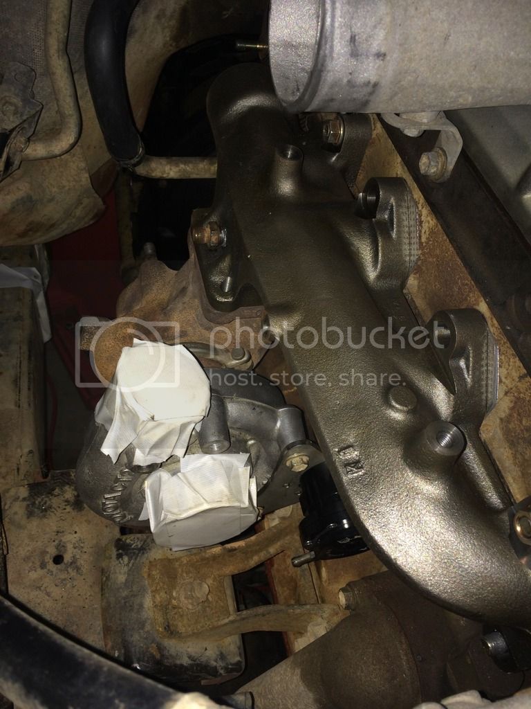
I have a used standard Toyota turbo from a 100 series 1hd-fte. I have fitted a Supra 7MGTE front compressor housing to simplify connecting the intake. This turbo should give decent low end response, and reasonably high flow at modest boost numbers (for a stock turbo).
I have fitted a 1 bar waste gate actuator from Kinugawa turbo. (I had to re-drill the bracket to get it to fit)
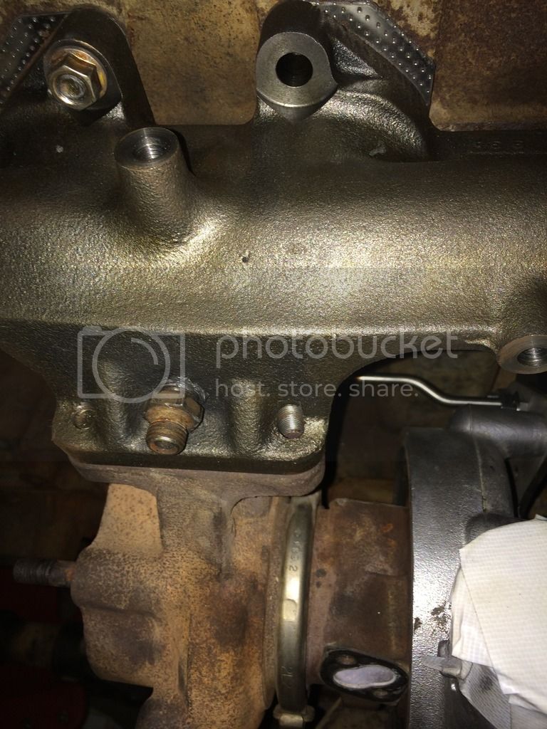
I purchased a new 1HD-T exhaust manifold front half from Amayama. I couldn't find a used one, and amayama's price was about what I'd seen them sell for second hand.
Manifold has been drilled and tapped for pre-turbo EGT probe.
Fuel pump
I will be running the stock fuel pump.
I will fit an aneroid/boost compensator to it to improve tuning options. (still looking for a bargain )
I will have an EGT probe pre turbo, and will install an AFR/O2 sensor in the dump pipe. (not sure if the dump pipe is the best place for the AFR sensor??)
Exhaust
I am in the process of fabricating a new exhaust system, I've run out of parts and parts shop is on holidays!!
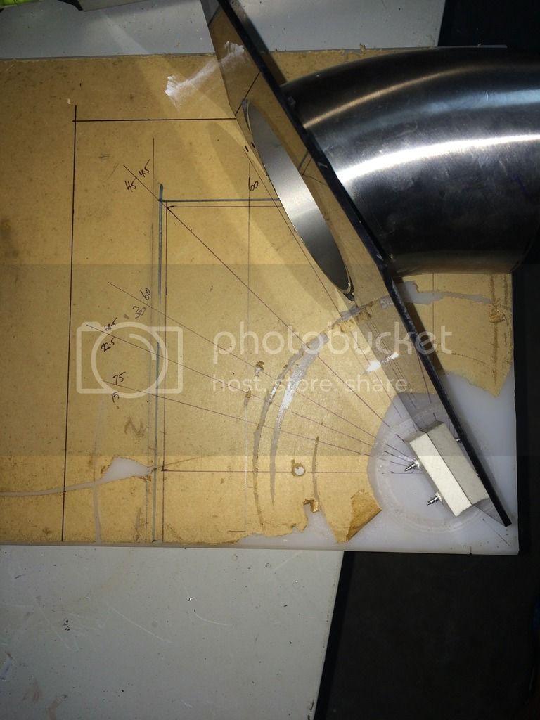
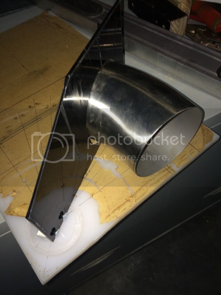
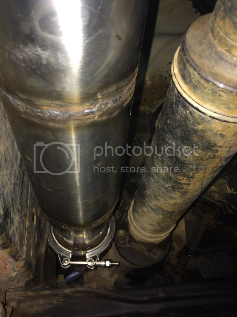
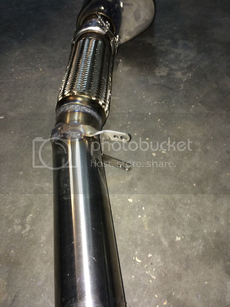
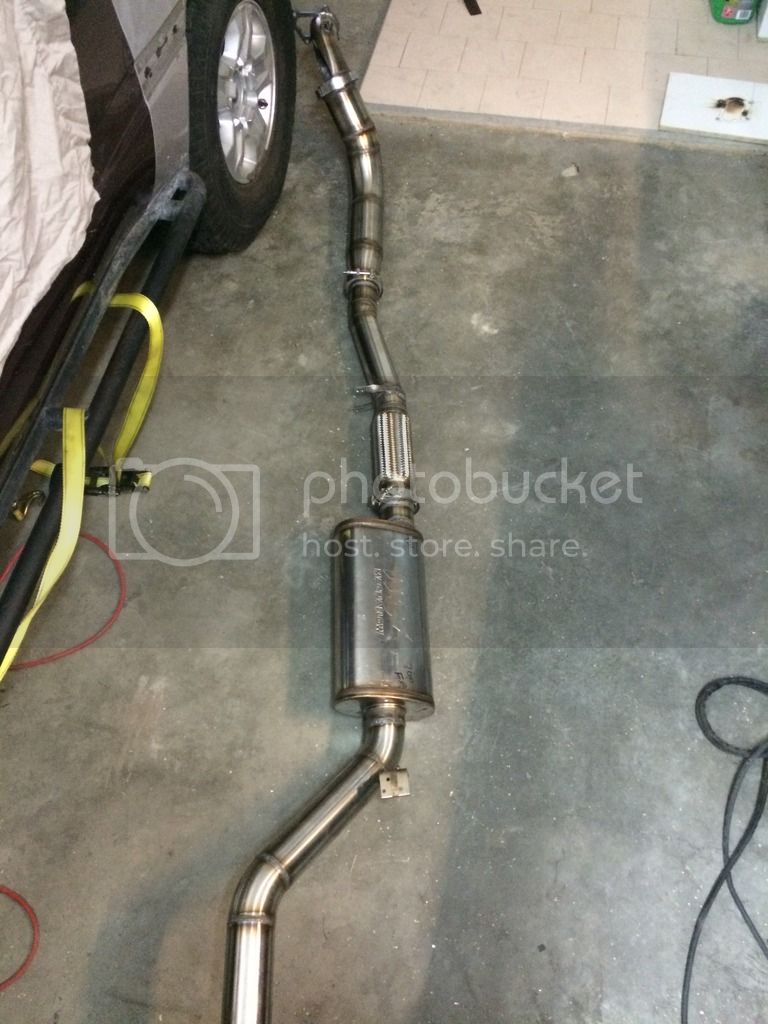
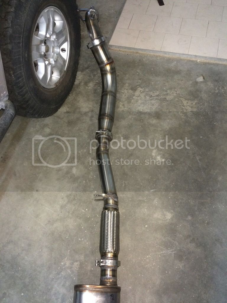
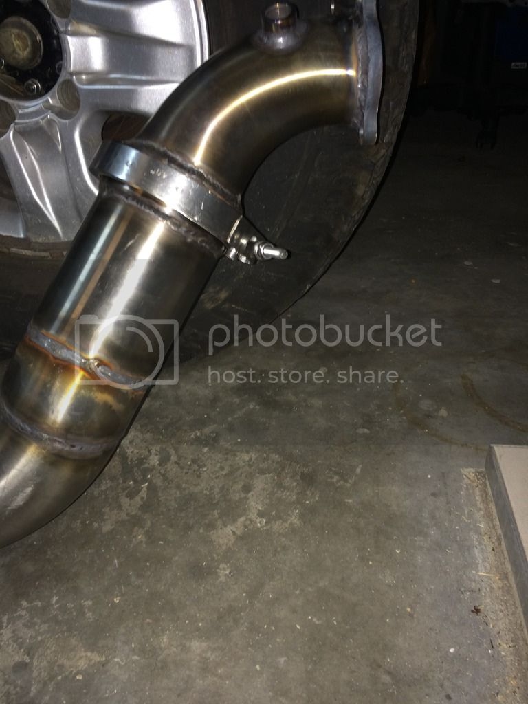
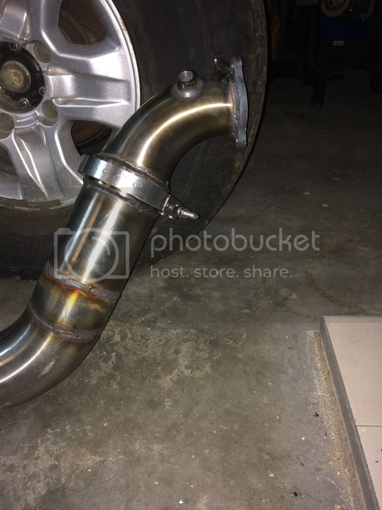
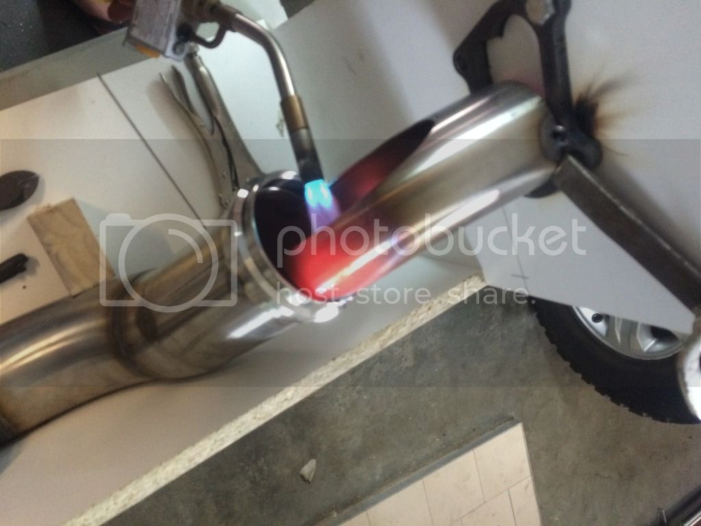
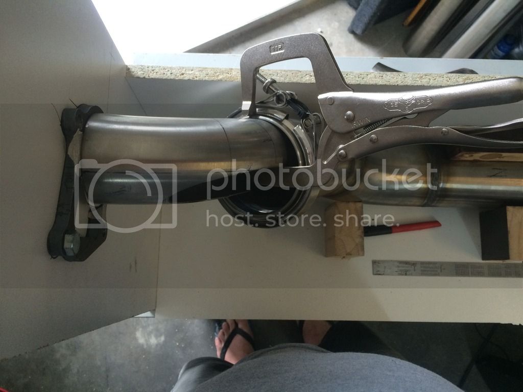
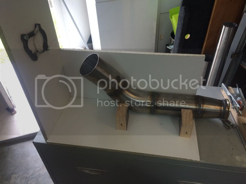
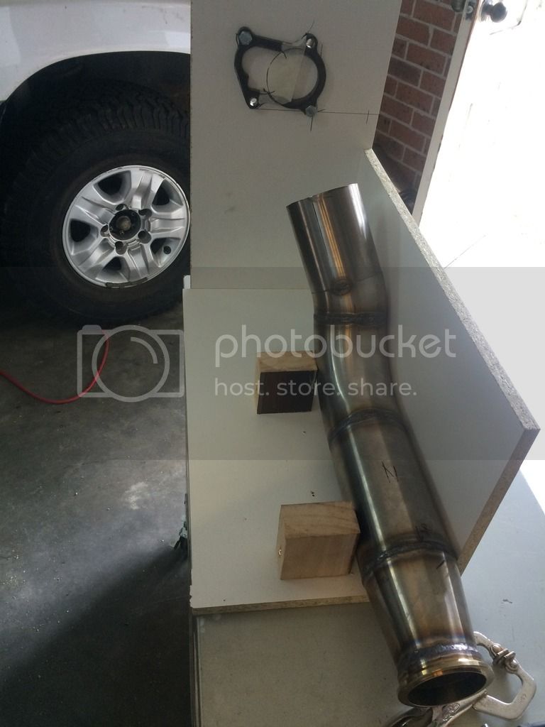
I have used 4" and 3" stainless pipe, and weld in mandrel bends, and v-band flanges. I have used a 3" and 2.5" elbow cut and shut to form the first bend of the dump pipe, and to separate turbine exhaust and waste gate exhaust.
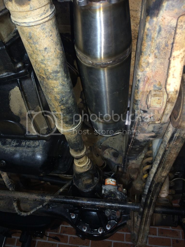
This joins to a 4" v-band flange, then 4" pipe and elbow to the transfer case.
(The reason for 4" dump pipe is to provide an expansion chamber so turbo can spool up with absolutely no back pressure. I did this on my HDJ81 about 10 years ago, and it seemed to work really well, so figured I'd do the same again.)
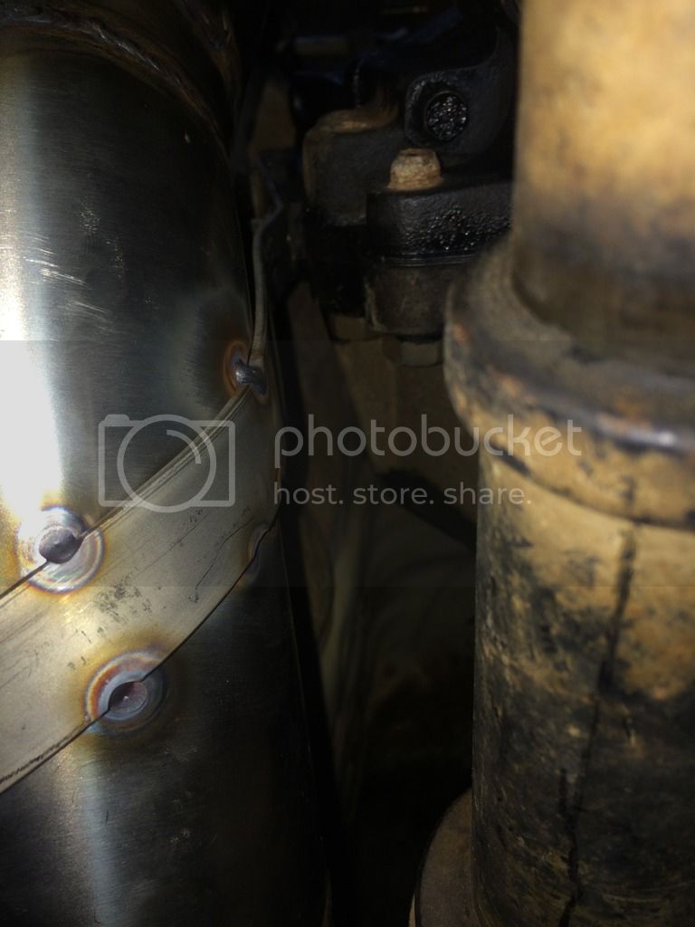
At the transfer case, the pipe tapers to 3" to pass between the transfer and the chassis, I had to cut a lug off the side of the transfer for clearance. This section will all be hard mounted to the transfer case, so minimal clearance from the transfer is needed.
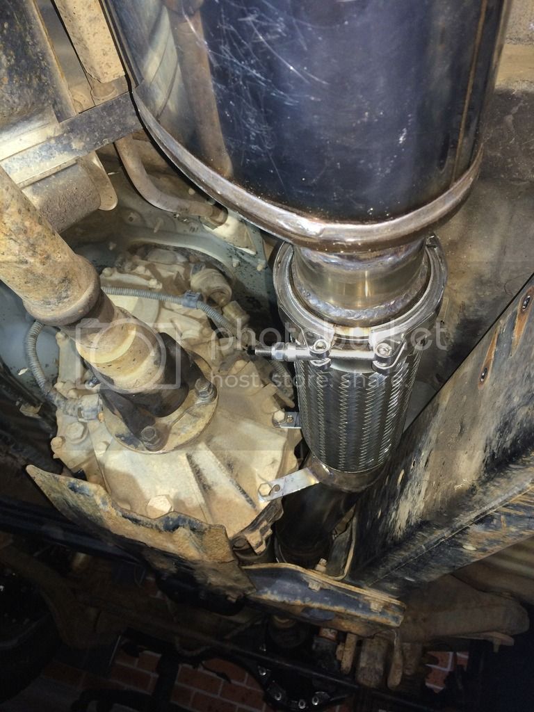
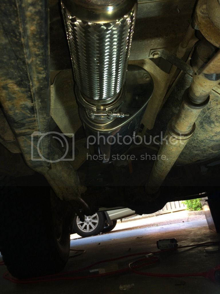
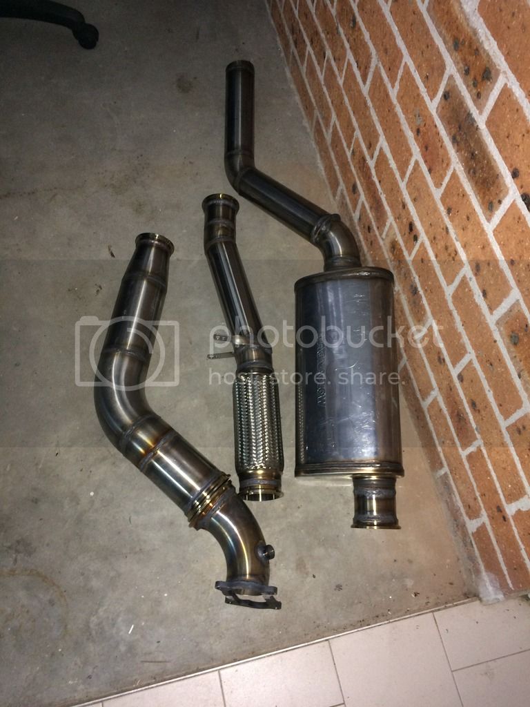
After the transfer case I have a 8" braided flex, then a 6x9x16" full flow muffler, before turning up over the rear diff, and out past my 90 litre Prado rear sub-tank, then into a 6x14" round full flow muffler at the rear.
The exhaust after the braided flex is mounted to the chassis using the Toyota brackets and rubber block mounts. I have kept minimum of 10mm (3/8) clearance to the chassis. with the 8" flex, this should be enough clearance.
My aim was to fit the largest mufflers I could, and use bends no greater than 45 degrees if possible and keep everything above the chassis rails. I will achieve this except for 60 degree bends for the dump pipe, and one 60 degree bend to get past my sub tank.
I've used several v-band flanges, as the last system I built for my HDJ81 was a complete ballsack to get in and out, so I've made this one in shorter pieces.
Intake
I will eventually make a 3" stainless snorkel, into a HDJ100 series air filter housing.
I intend to fit a 600x300x75mm FMIC, or possibly larger if I can. I will again aim to minimise bends in the intake tract, and keep it as short as possible. If I have to put a holesaw through sheet metal, so be it my cruiser has been used and abused, and is no stranger to the 5" grinder and MIG, so its far from pristine.
I will eventually make up a custom intake manifold too with a larger plenum, and possibly bellmouths into the intake runners.
Pics to come.
This is a slow moving project as I am working away from home, so don't get much time in the shed.
A bit of back story:
My cruiser has been parked up for nearly two years already after the engine boiled and I discovered a cracked head, and blocked radiator due to mixing incompatible coolant types.
I got lucky and the bottom end had no damage, so I re-co'd and fitted a used head, all new cooling system including radiator, thermostat, heater core, hoses etc.
With the engine, I pulled the head, fitted a second hand head, cleaned up and lapped the valves, dropped the sump and cleaned out all the oil and water sludge and checked for white metal in the oil.
No sign of bearing metal.
Cylinder walls were all in good condition, as were piston crowns.
I put it all back together and turned it over with the injectors out. Oil pressure came up fairly quickly. so I put the injectors back in and got it running. After the IP and injectors were rimed, it fired up and ran pretty well straight away, though a little tappy up top. after running it up to operating temp it started sounding a little better.
After shutting it down, I pulled the rocker cover and went through and measured up for new valve shims, which I still have to fit.
so, seems like I dodged a bullet with the engine. I've since driven it 200km to relocate house, and it ran sweet.
While its been off the road, I did a full rebuild on the front end. New bearings and seals in the knuckles, new CV/birfield in left side (I'd blown one up and been running in rear wheel drive for a while), new DBA T3 rotors, new pads, new wheel bearings, rebuild kit through the calipers, fitted braided lines on the brakes, new TRE, new knuckle/steering arm studs and cone washers, new hub studs and cone washers etc. Re-fitted my rebuilt front factory locked diff centre, and upgraded the 3rd member studs and bolts to 10mm (the standard 8mm studs are known to fail).
Also re-did the rear brakes, wheel bearings etc, and fitted new uni joints in both driveshafts.
While my cruiser was parked up, it got wet inside and ended up all musty. I striped all the interior out (except the dash), threw out carpet underlay, and pressure washed the carpets, and scrubbed everything else clean.
While the interior was out, I added dynamat sound deadener to as many flat panels as I could including the underside of the roof, doors, quarter panels and floor. I then added a layer of 6mm, foil insulated closed cell foam for some heat and noise insulation.
Then I refitted the interior.
My cruiser is sort of stock
 it's been wheeled failry hard, I think one or two panels have no dings.
it has 2" lift, with slotted/drilled bushes in the radius arms, and modified shock mounts and longer shock for an extra 60mm shock length front and back. No front sway bar, kept the rear to get sway bar in to make the front suspension flex.
The aim was for the travel of a 4" lift,with out the height.
285/75r16 All Terrains for daily use, and 315/75r16 for playtime on 1"offset rims.
5 speed manual trans (R151, possibly upgrade this later)
4.31:1 diff gears.
ARB rear locker, toyota e-locker in the front, (I had an e-locker in the rear from an 80series, but different axle specs caused me issues) lockers are set up to be switched individually, so front only can be used.
I cut out the sills/rockers and welded in a tapered RHS section with sliders built in, this gives great ground clearance with some protection from rocks.
I also built a rear bumper/tire carrier with similar ideas to keep ground clearance as high as possible.
Rolling the dice.
Over the past couple of weeks, I decided to go ahead with fitting a turbo. This is something I have wanted to do since I bought this car. My previous cruiser was a HDJ81 factory turboed 1hd-t which I had tuned up quite a bit (pre Gturbo days). The HZJ105 just doesn't live up to the power of a tuned up 1hd-t.
Turboing the 105 series 1HZ's is considered to be a gamble (hence "Rolling the Dice"). They have lighter pistons than earlier 1HZ's, and many people recommend NOT to turbo these engines. There are plenty of success stories, and plenty of cracked heads, cracked pistons, and hoed pistons, and overheating problems etc etc. Some people will say once turboed, the fuse has been lit?
I think that lots of these engines aren't turboed properly. They aren't tuned with regard to EGTs and AFRs, they are either tuned for power, and run too hot. Or they are tuned "conservatively" and run 7-10psi in the belief that too much boost is what kills the engines. Or they run poorly matched turbo's. Often they aren't intercooled.
A lot of these things can be avoided, and managed better than is often done.
My Plan is to wake up the 1HZzzzzzzzzzz, without going too stupid on it. I want it too last,so will be a little more conservative than I have in the past.
I will a boost compensator, intercooler, EGT, AFR, Oil pressure, and water temp guages fitted up before this is put into use.
I like to look for bargains, and alternatives to keep the cost down without doing stuff too much on the cheap. The end result has to live up to expectations.
Turbo
I have a used standard Toyota turbo from a 100 series 1hd-fte. I have fitted a Supra 7MGTE front compressor housing to simplify connecting the intake. This turbo should give decent low end response, and reasonably high flow at modest boost numbers (for a stock turbo).
I have fitted a 1 bar waste gate actuator from Kinugawa turbo. (I had to re-drill the bracket to get it to fit)
I purchased a new 1HD-T exhaust manifold front half from Amayama. I couldn't find a used one, and amayama's price was about what I'd seen them sell for second hand.
Manifold has been drilled and tapped for pre-turbo EGT probe.
Fuel pump
I will be running the stock fuel pump.
I will fit an aneroid/boost compensator to it to improve tuning options. (still looking for a bargain )
I will have an EGT probe pre turbo, and will install an AFR/O2 sensor in the dump pipe. (not sure if the dump pipe is the best place for the AFR sensor??)
Exhaust
I am in the process of fabricating a new exhaust system, I've run out of parts and parts shop is on holidays!!
I have used 4" and 3" stainless pipe, and weld in mandrel bends, and v-band flanges. I have used a 3" and 2.5" elbow cut and shut to form the first bend of the dump pipe, and to separate turbine exhaust and waste gate exhaust.
This joins to a 4" v-band flange, then 4" pipe and elbow to the transfer case.
(The reason for 4" dump pipe is to provide an expansion chamber so turbo can spool up with absolutely no back pressure. I did this on my HDJ81 about 10 years ago, and it seemed to work really well, so figured I'd do the same again.)
At the transfer case, the pipe tapers to 3" to pass between the transfer and the chassis, I had to cut a lug off the side of the transfer for clearance. This section will all be hard mounted to the transfer case, so minimal clearance from the transfer is needed.
After the transfer case I have a 8" braided flex, then a 6x9x16" full flow muffler, before turning up over the rear diff, and out past my 90 litre Prado rear sub-tank, then into a 6x14" round full flow muffler at the rear.
The exhaust after the braided flex is mounted to the chassis using the Toyota brackets and rubber block mounts. I have kept minimum of 10mm (3/8) clearance to the chassis. with the 8" flex, this should be enough clearance.
My aim was to fit the largest mufflers I could, and use bends no greater than 45 degrees if possible and keep everything above the chassis rails. I will achieve this except for 60 degree bends for the dump pipe, and one 60 degree bend to get past my sub tank.
I've used several v-band flanges, as the last system I built for my HDJ81 was a complete ballsack to get in and out, so I've made this one in shorter pieces.
Intake
I will eventually make a 3" stainless snorkel, into a HDJ100 series air filter housing.
I intend to fit a 600x300x75mm FMIC, or possibly larger if I can. I will again aim to minimise bends in the intake tract, and keep it as short as possible. If I have to put a holesaw through sheet metal, so be it
 my cruiser has been used and abused, and is no stranger to the 5" grinder and MIG, so its far from pristine.
I will eventually make up a custom intake manifold too with a larger plenum, and possibly bellmouths into the intake runners.
Pics to come.

 bit of a challenge, but really enjoyed it.