Problem with headlight upgrade? (1 Viewer)

This site may earn a commission from merchant affiliate
links, including eBay, Amazon, Skimlinks, and others.

Joined
Sep 24, 2012
Threads
94
Messages
504
Location
Seattle
This is for the electrically-inclined among you or for those who have done this upgrade:

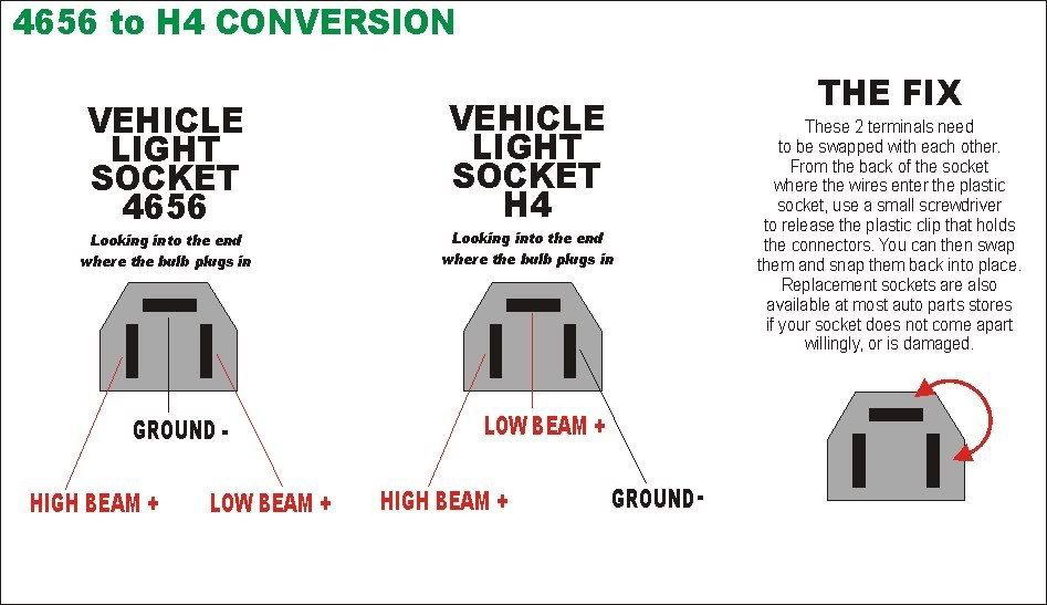
So I'm in the process of upgrading my 62's quad sealed beams to a H1/H4 setup, using the wiring diagram here. I am using Hella housings and lamps with stock equivalent wattage. Before connecting the new harness I built, I plugged the new lamps into the existing wiring harness. I did this on the driver's side only - I was curious about the new lamps' output compared to the sealed beams, which I left in place on the passenger side. Installing one side only lets me compare the two.

Everything works, but I noticed 3 odd things:
1) when activating the high beams, the new H4 low beam lamp dimmed to about 75%, while the existing sealed low beam stayed constant. The H4 goes back to 100% when the high beam is off.
2) with only the low beams activated, the high beam lamps glow faintly, both the new H1 high beam lamp and the existing sealed beam high beam lamp.
3) there is not much discernible light output difference between the two sides.

Again, this is using the existing wiring. Plug and play. I'll move ahead with the new harness shortly, which may bring its own surprise (and hopefully an improvement in light output), but I'm trying to troubleshoot this first step.
 
Are you using an adapter between the harness and H4? The sealed beam and H4 use the same shape connector, but a different pin layout.
 
Ah, good call on that, Doc! Of course. Now I recall that the pinout is different. When I use the adaptor in the Hella kit, all 4 lamps come on 100%, and activating the high beams actually turns them off, so apparently that adaptor does not compat. I'll need to rearrange the pinout on the car's connector.

Does this look about right?

4656toH4Conversion.jpg
 
Last edited:
I didn't pay much attention to the Hella kit adapters (same as you show), since I was making a custom harness assembly anyway. Having tried the adapter, it does not seem to work in my case, but I'm beginning to wonder whether it's because at the moment I have the new H1/H4 lamps on one side the and the old sealed beams on the other. Since they're pinned differently, I wonder whether voltage might be back-feeding across the two circuits and causing the problem I see.
 
UPDATE

Both sides are now symmetrical with H4/H1 lamps installed and running off the original circuits. I have not yet energized my new upgrade harness. I have re-pinned the original headlight connectors to work with H4 lamps, making it unnecessary to use a 4656-to-H4 adapter. The H1 lamps don't need an adapter - they only have 2 pins: 12V+ and ground.

When I installed earlier today, everything seemed to work fine. However, the H4 (low beams) still change their output when the H1's (high beam) are activated.

Tonight, starting up the truck after the install, the H1's (high beam) would not turn off. Pulling or pushing the stalk simply changes the output of the H4 (low beam) in the way I describe above, but the H1 (high beam) will not turn off at all unless I turn off the H4. It's all 4 lamps or nothing.

Anyone have any ideas? I double-checked my re-pinning job on the H4 connectors and it looks right. Eventually, I'll switch to my new circuit, but it seems odd that this is happening on the original circuits.
 
You fried the headlight switch drawing too much current. Should of installed the harness first. You can open the switch and file the contacts.
 
You fried the headlight switch drawing too much current. Should of installed the harness first. You can open the switch and file the contacts.
How is that possible? The H4/H1 kit is plug-and-play. Doesn't require an upgraded harness. Same wattage as the sealed beams. Also, wouldn't the fuse protect the switch?
 
The switch is a wear item. All mechanical relays/switches arc every time power is switched. Over time this builds carbon on the contacts and close proximity. Eventually shorts may occur or insufficient power transfer through the contacts.

My understanding is the switch in the steering column is a weak link for our headlights. When I got my truck I had HI only. Low appeared non functioning. I opened the switch in the column and filed contacts, cleaned with electrical solvent and my HI LOW work as intended (factory stock setup still).

Whether or not this is your problem, I dont know?

Do you have a multimeter? Measure for voltage at the headlight harness not plugged in to a bulb, then measure voltage (if possible) with it plugged into the bulb, the difference should be negligible.

Disconnect battery, insert key and switch to on, turn on lights. Now measure ohms from harness to NEG battery connector. Ohms from harness to positive battery connector for both HI and LO.

Take notes. Have the FSM schematic?

It should now become clear what is happpening.. if not post details here.
 
just FYI, my harness uses #4 primary + from alt to battery to relay box, and #4 - from battery/ground to headlight harness. there is alot more small wire in the factory circuit than one would think(voltage drop). you could prolly use #8 or even 10. Follow the schematic exactly; use the factory wires to trigger the relays only.
 
Took apart the steering column switch assembly. The Hi/Low stalk switch looks like brand-new. No carbon deposits, scorch marks, or gunk. I verified that all the contacts were engaging and disengaging, and touched them up with a bit of 600 emory cloth just in case. No difference. Hi beams still will not disengage.

Where is the Hi beam relay located?
 
a1.jpg

Lights have 12V always. AFAIK the switch you just took apart and cleaned IS the 'relay'. This switches the NEGATIVE so either lo or both hi and lo have continuity to ground.

Sounds like you are supplying the NEG directly, expecting to switch +12V, which is not the case. Hard to say without being their.

A multi meter is your friend and will tell you the answer if you use it.
 
there...
 
the filament of a lamp is a resistor- you are feeding voltage thru the OFF lamps to the other lamps, it seems...the new harness should do this: with lo beams ON, the headlight switch is closed, and feeds 12 volts to the hot side of the relay bank; at this point, relay 1 and 2 are energized via headlight switch and bonded grounds, while relay 3 and 4 remain off due to the position of the dimmer switch(no ground to relay coils at this point...) in this position, relays 1 and 2 will be closed, supplying power to the hot side of the LOW BEAM lamps, illuminating them via the ground thru the normally closed contacts of the dimmer relay(relay 3). at this point, the high beams of all 4 lamps will be off due to LACK OF GROUND via dimmer relay(relay 3). there should be NO illumination of ANY KIND on the high beam filaments in this position, or the indicator lamp on the dash as it should have ground on BOTH OF ITS TERMINALS- therefore NO CIRCUIT. when the dimmer switch position is changed to HIGH BEAM, the dimmer relay is energized, opening the path to ground from the low beam filaments(fed by relays 1 and 2), and closing the path to ground at the high beam filaments(fed by relays 1 and 2) to the DUAL STAGE lamps, causing the dual stage lamps to turn HIGH on their high beam filaments, and LO(off) on their low beam filaments. With the dimmer relay closed to its NORMALLY OPEN position(high beams), the indicator lamp now has +12 on one side, and ground on the other, and it WILL illuminate; WHILE the dimmer switch is closed, the HIGH BEAM relay(relay 4) also has power and will now switch 12 volts+ to the high beam buckets, illuminating them via their bonded grounds.

using this harness requires using ONE of the low beam headlight FACTORY SWITCHED wires to provide +12 volts to the relay banks coils hot sides- the one factory switched wire feeds 12 volts positive thru the headlight switch to the hot side of each relay. the wire from the dimmer switch is a factory SWITCHED GROUND wire and is used to feed ground to relays 3 and 4 at the same time. A 12 volt circuit is used to feed BOTH DUAL STAGE BUCKET relays switched contacts, and therefore BOTH dual stage buckets. An additional circuit is used to feed power thru relay 4 to the HIGH BEAM BUCKETS. A BIG GROUND is fed directly to all points of use.


relays 1 and 2 are switching NEW circuits via fuses from +12 volts to feed the DUAL STAGE buckets
relay 3 is switching GROUND
relay 4 is switching NEW circuit via fuse from +12 volts to feed the HIGH BEAM buckets

headlight switch is switching HOT
dimmer switch is switching GROUND


HTH
 
wired correctly will have zero cross voltages...
 
you are only going to use ONE of the TWO low beam factory wires, and the ground to the high beams from the dimmer switch to operate the new harness...oh, and relay 1 and 2 will have direct to ground bond...so 3 wires total to operate the new harness; if you have more factory wiring bonded into this than that, start there to find your extra jumper...
 
SECOND UPDATE:

So, I returned everything back to factory in sequential order and got some interesting troubleshooting results (I was careful to correctly re-pin the lamp connector when alternating between 4656 and H4) -

New H4 + old sealed hi beam = everything works fine
old sealed low beam + old sealed hi beam = everything works fine
Conclusion: switch/harness/relays are probably not borked

Then, just for s***s and giggles, I put back the H4/H1 setup I had when I started this thread and...it all works fine.

Now, normally I'd blame this on some wiring cock-up I'd be prone to, but the exact same thing happened when I originally went through this days ago and again yesterday when I did the install I'm posting about now. The H4/H1 setup works fine until at some point the hi beams refuse to turn off. Twice, that point has come only after I started the engine (but not consistently). Swapping the sealed hi beams back in seems to have cured that 3 times now.

Thoughts?
 
you know what, I lied...the explanation I gave above does detail the SLCFJ62 harness diagram, but I am running a slight variant of it- err um, a basic HI/LO relay operated flip flopper, utilizing OEM harness to trigger
relaysled.jpg
relaysled.jpg
relaywiring_3.jpg
relaywiring_2.jpg
relaywiring_1.jpg
wiring_1.jpg


so the idea is 3 relays and 2 20 amp circuits; 1 relay EACH SIDE to operate power to both buckets., and one relay to flip/flop ground from HIGH side to LOW side. the relay harness is built as a stand alone harness with 3 wires to tap into the OEM lighting harness and of course, power and ground. My harness uses #4 from the battery hot to the alt battery post and ground to a ground post by the relay sled, and a # 10 from the alt to the aux fuse box. this should overcome the voltage drop issues the factory harness had...and it is a bit much, but I had it around...the relays feed power and ground to a 12 gauge harness to go to both sides lamp buckets. the hot sides are shared at the buckets of both the dual stage and high beam buckets on either side. I figured 20 amps should be more than enough- about 240 watts on each side worth. I get 12 volt hot to the coil of ALL 3 relays using the OEM red with white stripe. this seems to be 12 volts+ from the headlight switch. I spliced into the OEM red with yellow wire(factory HI beam ground) to operate the relay for HI/LO. the high beam indicator is powered by tying the ground from the LO BEAM side to the OEM red with green stripe(factory LO beam ground). I spliced into the OEM harness in the last stretch before the drivers side headlight buckets,and left it intact, otherwise.
 

Users who are viewing this thread

Back
Top Bottom