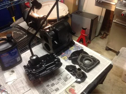
H42 Transmission, Tcase, eBrake Rebuild in a '76 FJ40`

This site may earn a commission from merchant affiliate
links, including eBay, Amazon, Skimlinks, and others.

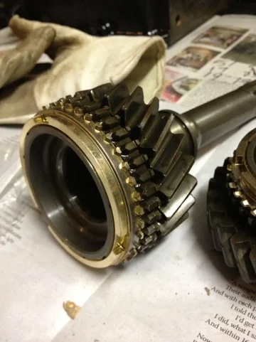
Ordered the two synchros (#3 and #4) from Onur at Lowe Toyota today. About $35/each. Will post part numbers once I have them.

These are the small brass ones between 3rd gear on the output shaft, and 4th gear on the input shaft. They are the same.

The other two are discontinued I believe, and are much thicker.

The other two are in fact one large part containing the two baulk rings,the 1-2 shift hub and reverse gear. It's better to buy a used low-miles trans than buying the sync assembly:

Toyota Part:
RING SUB-ASSY, SYNCH
Part NO.: 33306-60010
Your Price:
$547.50
Toyota's Retail Price:
$746.47
You Save:
$198.97
 
The other two are in fact one large part containing the two baulk rings,the 1-2 shift hub and reverse gear. It's better to buy a used low-miles trans than buying the sync assembly: Toyota Part: RING SUB-ASSY, SYNCH Part NO.: 33306-60010 Your Price: $547.50 Toyota's Retail Price: $746.47 You Save: $198.97
. Yep, I'd bet you can get two trannys for that. Good to know they are available.
 
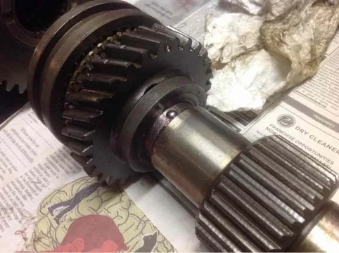
Ok got the new synchros from Beno/Lowe Toyota (took about 10 days), and restarted the re-assy.

image-2187384502.jpg

image-4072702274.jpg

image-921702007.jpg
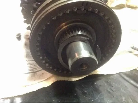
Synchros 3 & 4 in place

Step 15.

Put the bearing on the input shaft, along with the old, small retaining clip. Used a 2" ID PVC pipe to tap the bearing into place. Was able to hold the shaft in my hand while tapping it on. It slid on pretty easily.


image-3912151932.jpg


image-209175201.jpg
Bearing 6308N
image-2187384502.jpg
image-4072702274.jpg
image-921702007.jpg
image-3912151932.jpg
image-209175201.jpg
 
Last edited:
Working on the Transmission Case Cover Assy tonight. Question: where does this interlock pin go?

FSM says this:

image-4074683183.jpg
But his hand is just floating in space.


image-1333868454.jpg
Exploded Parts. Figure 3-53 is pointing to the pin.

When taking it apart, these just fell out, so I have no idea how they fit.

Where does this first one go? Looks like the hole here the shaft is going in, but how?

image-1132487598.jpg
Bottom left area

image-2097107463.jpg
Blue punch is pointing at the pin.


image-3944756834.jpg
View of the indents in the shaft
image-4074683183.jpg
image-1132487598.jpg
image-2097107463.jpg
image-3944756834.jpg
image-1333868454.jpg
 
The interlock pin goes in between two of the sliding shafts so that there is only room for one of the shafts to slide when both are in N.
 
The interlock pin goes in between two of the sliding shafts so that there is only room for one of the shafts to slide when both are in N.

So it fits perpendicular to the two shafts. How do you get it in there? I see the hole, but scratching my head on re-inserting.

EDIT: Got it. It slips right in. I just used a finger in each hole (minds out of the gutter) opposite the interlock pin hole and the pin slipped in.
 
Last edited:
Mind is definitely in the gutter but resisting the urge to put those thoughts in writing.

Great thread! I am working on my 2f now but then it's on to the trans and transfer case.

simple is usually right... 1973 fj55
 
Step 16

Reassemble the Transmission Case Cover Assembly

Followed the FSM. Actually used the 1975 and the 1980 FSMs to make sense of re-assy order. 1980 has a different order, wants you to put the shift cover on first and start with the ball bearings and the springs, whereas in the 1975 FSM, those are last. I did follow the 1975 since that is the model year that my transmission looks like this one the most closely, even though I'm not sure that mine is any different from the 1980.

image-4016745251.jpg
1975 Assembly Order

image-3223269098.jpg
1980 Assembly Order

I actually had to take the photo from the 1975 book above, and turn it upside down to determine how to arrange all the parts for assembly. The exploded parts diagram was in one orientation, and the photos were in a completely different orientation (flipped and rotated 180 degrees). Plus there was not a complete photo of the orientation of the forks so I had to keep going back to the exploded parts drawing. It's like the 1975 is missing some steps, but I guess they expect you to know what you are doing.

Once I figured out the orientation of all the parts, it was pretty simple.

Be very sure the shafts are oriented properly before you drive in the spring pins. Taking them out is a little tough and makes me nervous. The pins did drive in fairly easily, though one was cracked on the end from removal.

Remember to put some grease on the interlock pins that will also help hold them in place during assy. Grease or put gear oil on the shafts and all other components before assy.

image-3539455492.jpg
image-1048132836.jpg
Lining up the holes for the spring pin

image-4068544393.jpg
Completed bottom

image-3069965546.jpg
Completed top

I reused the old expansion plugs. Wire wheeled them clean, put RTV on them, and tapped them in with a big brass drift. You can go up to 3mm deep.

image-2066961478.jpg
image-161754739.jpg
Completed Expansion Plugs
image-4016745251.jpg
image-3223269098.jpg
image-3539455492.jpg
image-1048132836.jpg
image-4068544393.jpg
image-3069965546.jpg
image-2066961478.jpg
image-161754739.jpg
 
Last edited:
Step 16 Cont

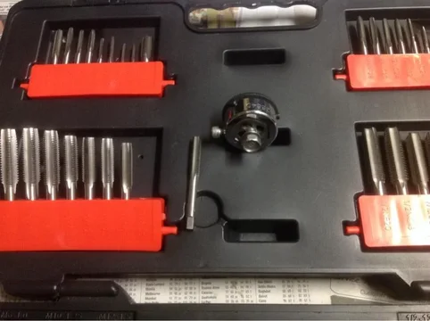
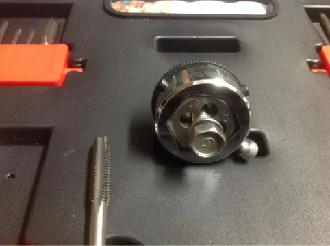
Cleaned up the gear shift cover bolts on the wire wheel, then chased the threads and bolt holes with the tap and die set. Laughed at myself for spending 15 minutes per bolt/hole on a $300 tranny that many would assume throw away and buy another. It's about the journey.

image-1227839874.jpg
image-2896235116.jpg
Die on the Bolts

image-4082062318.jpg
Tap on the holes

I appreciate the ease of the ratcheting driver that works on taps and dies alike.

image-3147928711.jpg
Great set. Worth the price, and I'm just getting started on this FJ40 rebuild.

Cleaned up the springs on the wire wheel. Hmmm, forgot to grease them. Dang. Oh well, they will get a little from the balls and I can get some up in there from the bottom if I lube the shafts and turn the assy upside down, right?

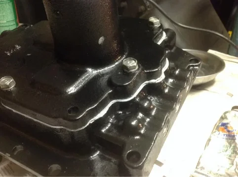
Cleaned the mating surfaces with brake cleaner after lubing the inside of the tranny top and the inside of the shift cover plate with some gear oil to keep the flash rust away.

Inserted the detent balls and springs, slathered a thin layer of RTV on the gasket faces, and bolted down 5 of the 6 bolts on the shift cover plate. I left the one bolt out that holds the shift guide for the 4WD for the transfer case, IIRC.

Feel like I finally made some progress again on this.


image-727507607.jpg


image-2548048006.jpg


image-262688646.jpg


image-256275662.jpg
image-1227839874.jpg
image-2896235116.jpg
image-4082062318.jpg
image-3147928711.jpg
image-727507607.jpg
image-2548048006.jpg
image-262688646.jpg
image-256275662.jpg
 
Last edited:
I wish I was doing my H41 after reading this thread...

(But it doesn't misbehave or even make any strange noises... Damn!)


:D
 
Step 17

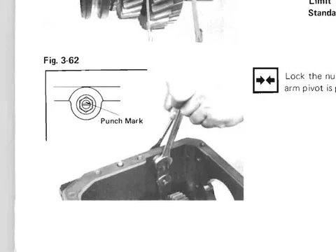
Attach Reverse a Shift Arm to the case. Line up the punch mark or slot on the bolt to be on top. Mine has a slot on it.

ImageUploadedByTapatalk1385262774.778101.jpg
FSM

image-2296713152.jpg
BOLT ORIENTATION

The bolt needs to be oriented as seen here. I mimicked the angle it was when I took it apart which was off a few degrees. If it doesn't t shift well, I'll put the slot at zero degrees or adjust it until it shifts well. Put some gear oil on everything.

image-3238365733.jpg
Bolt Head orientation - flat areas vertical or nearly so

Then I inserted the Reverse Idler shaft, key and gear. Oiled the shaft, key and gear. Tapped in with a leather hammer.

ImageUploadedByTapatalk1385263748.383366.jpg
Shaft and Gear

Ensure the foot of the arm goes in the gear slot.

image-2435923302.jpg
Shaft and Key
ImageUploadedByTapatalk1385262774.778101.jpg
ImageUploadedByTapatalk1385263748.383366.jpg
image-2296713152.jpg
image-3238365733.jpg
image-2435923302.jpg
 
Last edited:
Step 18

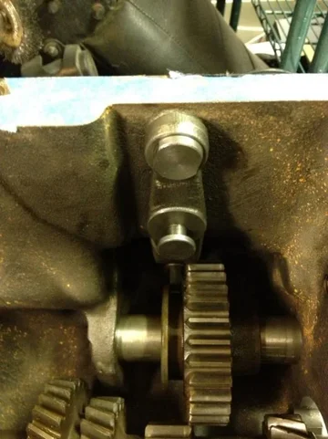
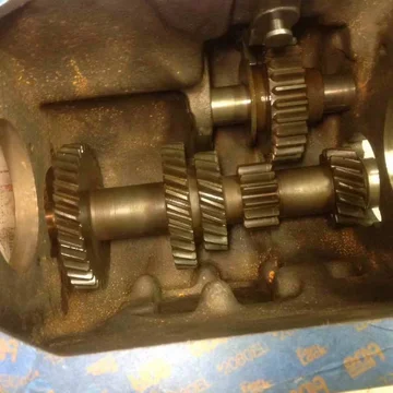
Place Counter Shaft into the case as shown.

ImageUploadedByTapatalk1385269904.064663.jpg

Just lay it on the bottom of the case so you can get the main shafts in.

Assemble the main shaft. The FSM shows the order.

The little ball bearing and the small pin fit in the following manner:

ImageUploadedByTapatalk1385270038.200420.jpg
Ball bearing - shown without 2nd gear in place. Fits under the bushing in the slot in both the shaft and in the bushing.

Next photo shows with 2nd gear in place.
ImageUploadedByTapatalk1385270212.381234.jpg
With 2nd Gear

Put the remaining parts 9-13 on the shaft.
ImageUploadedByTapatalk1385270300.968331.jpg
FSM

Fit the pin in the slot n the shaft by first gear. Fit the thrust washer (13) over the pin.
ImageUploadedByTapatalk1385270331.480528.jpg
Pin next to the hole. Round side goes in. Flat side up.

ImageUploadedByTapatalk1385270457.220227.jpg
Thrust Washer in place, over the pin.
ImageUploadedByTapatalk1385269904.064663.jpg
ImageUploadedByTapatalk1385270038.200420.jpg
ImageUploadedByTapatalk1385270212.381234.jpg


ImageUploadedByTapatalk1385270300.968331.jpg


ImageUploadedByTapatalk1385270331.480528.jpg


ImageUploadedByTapatalk1385270457.220227.jpg
 
Last edited:
Step 18 Cont

I forgot one key step on the input side of the main shaft. You must put the snap ring on to hold 3rd gear and second and the synchros in place. It is easier if you do it before putting on the synchro ring assy and first gear.

ImageUploadedByTapatalk1385270906.666867.jpg
Snap Ring

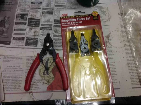
You need one of these. I don't have on and am stuck for the moment.

ImageUploadedByTapatalk1385270955.351212.jpg
Snap On SRP2A, Knipex 4510170, SK 7637, SK 7635 all seem to fit the bill

These do not work for this type of beefy ring (got it off, won't get it back on)
ImageUploadedByTapatalk1385271164.305101.jpg
ImageUploadedByTapatalk1385270906.666867.jpg
ImageUploadedByTapatalk1385270955.351212.jpg
ImageUploadedByTapatalk1385271164.305101.jpg
 
Snap rings have holes in the end for snap ring pliers to engage.

The ring with no holes is called a lock ring. The tool to remove is called (wait for it...)
Lock ring pliers.
spin_prod_206673501


Readily available at local Sears store.
 
FWIW, the best lock ring plier I've seen is the SK 7637 (and knockoffs) mentioned above. Opens linearly, instead of an arc, so it really helps avoid that 11 pm cursing fit when you're cold and tired and the ring launches off into the void and the dog runs back into the house...

Nice writeup! Thanks!

Thanks for that. I almost ordered those SKs via Amazon last night. Went with the Knipex. Hope they work. Noticed the Snap On ones had a divot in the blade to hold the end of the lock ring. Liked that idea.
 
Step 18 Cont

Received Knipex Lock Ring pliers. Installed lock ring in about 6 seconds. Sometimes you just have to have the right tool (foreboding for later in the post).

image-4048989768.jpg
Knipex

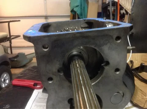
I changed the birdcage bearings (after forgetting to at first), and then dropped the now completed shaft into the tranny. The counter shaft was inserted earlier.

image-4033875361.jpg
image-2098358351.jpg
After dropping the shaft into the case.

Put on the output bearing and tap into place with a plastic or leather hammer,or a brass drift. DON'T just tap it in like I did and dance a little jig.

image-4114731530.jpg
Output bearing first.

No, the great tranny troll does not give up his secrets so easily. You must remember to brace the input side with a wrench or the shaft will not drive onto the bearing and won't allow the input shaft to be inserted. I of course didn't do this at first. Had to drive the bearing and shaft back about an inch, brace it and begin again.

Tap bearings all around the circumference - 12 o'clock, 3, 6, 9, or 12, 6, 3, 9 so it doesn't bind or drag. For these top bearings I used the leather hammer.

image-3087474447.jpg
Brace it!

Now, insert the needle bearings into the input shaft cup, securing with grease. Luckily it was fricking freezing in the garage so the grease was like tar.

image-3030466965.jpg
Needle bearings

Insert the input shaft onto the output shaft and tap the bearing on.

image-2996965570.jpg
image-1388273700.jpg
Almost there!

Once I got this, I pumped my fist and gave a big Hell yea! I was moving now!
image-4048989768.jpg
image-4033875361.jpg
image-2098358351.jpg
image-1350874770.jpg
image-4114731530.jpg
image-3087474447.jpg
image-3030466965.jpg
image-2996965570.jpg
image-1388273700.jpg
 
Step 19 - Counter shaft bearings

Start on the output side. Lift the counter shaft thru the square hole in the side of the case if you have one (I did not, what a pain). Start the bearing carefully with a plastic hammer.
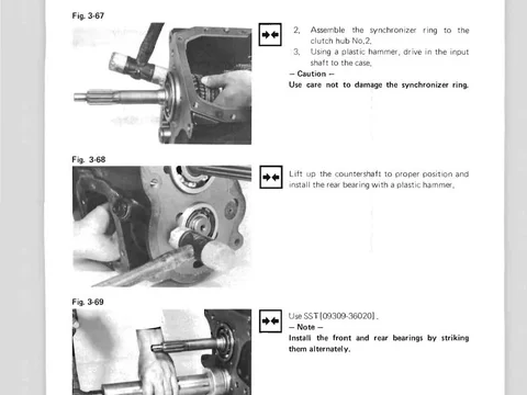
image-234621572.jpg
Counter shaft bearing Output side

Hmm, easy peasy, right?

Right.

image-1882752031.jpg
Tapped that sucker right in

Start the Input side bearing. FSM says you'll need to tap the two bearings in an alternating fashion.

See, look here, just a simple single photo and one line of text.

image-406023448.jpg
FSM is evil

After tapping the two bearings back and forth for about an hour, moving from soft hammer to big brass drift and 3lb sledge, I couldn't get the bearings closer than 7 mm. One side would go flush, then the other side would stick out 7mm. Damnit!

image-1212277413.jpg

image-2652867963.jpg
7 lousy mm

I finally had the idea to attach the bearing retainer with long bolts, and put the old bearing over the new bearing on the output side to hold it so I could tap the other side into place.

image-1438111930.jpg
image-1222121756.jpg
Bearing retainer output side

This is where I effed up. Big time. I noticed that the bearing on the input side was just bouncing back now when I hit it. Before, it would move easily. Also, I noticed the main and counter shaft would not turn all the way around without hitting a snag. Hmmm, what's going on?

Lesson: don't just hit it harder. As I did this, a 1/4" long piece of hardened steel fell out of an opening in the side of the case. Oh, $h*t. I cursed for a couple of minutes, realizing I was so close to being done with this bastard, and now knowing I'd at least have to remove the lower bearings, and at most have to replace the counter shaft if I've broken teeth somehow.

I cleared off the cart, turned the tranny on the side, and.... Nothing. Hmmm. Then I turned it upside down and ... Tinkle, tinkle, tinkle. The horrible sound of bits, nay, chunks of metal falling out. Oh man.

I turned the case back and found about 15 pieces of metal chunks. Ok, off with the bearings.

image-3317570815.jpg
image-1330262594.jpg
A tranny's worst nightmare

So once I got the lower bearings back off, I immediately saw the problem: between the inner race of the bearing on the output side, and the small gear on the countershaft, I shattered the ridge of material by putting too much pressure on the race somehow. I needed to only move the outer race but when I braced the bearing in the retainer, the shaft must have put pressure where it should not have.

Either that or I assembled something incorrectly.
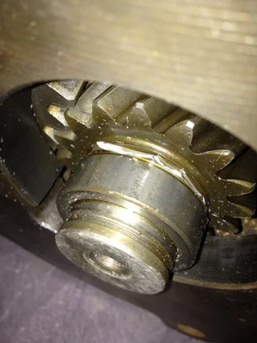
image-2470175521.jpg
image-1126850752.jpg
Shattered lip

This is what broke


image-798513683.jpg
Lip that broke

Question is - now what?
image-234621572.jpg
image-1882752031.jpg
image-406023448.jpg
image-1212277413.jpg
image-2652867963.jpg
image-1438111930.jpg
image-1222121756.jpg
image-3317570815.jpg
image-1330262594.jpg
image-2470175521.jpg
image-1126850752.jpg
image-798513683.jpg
 

Users who are viewing this thread

Back
Top Bottom