Gossamer... the saga continues (1 Viewer)

This site may earn a commission from merchant affiliate
links, including eBay, Amazon, Skimlinks, and others.

Joined
Feb 28, 2015
Threads
2
Messages
29
Figured I would start a thread keeping track of all the work I end up doing bringing this truck up to where I want it.

I got the truck back in November and planned to have a solid running rig with some of the things I would have done that I can commute to work in this winter then take out to the trails in the summer and fall. When I received the truck I figured out exactly how to start the thing then immediately loaded it up with my coworkers and took it out to see how it ran. The truck ran super strong so I commuted home and back the next day and noticed the was major wiring and oil leak problems I would address soon.

Coming off the shipping truck at work
image1.jpg


Firstly I had to address the wiring. The weather was still nice so I kept riding my motorcycle to work and pulled the truck in the shop and tried to make sense of it all. Anyone could start the car as there was simply a button pulling power right from the batter to the starter and the key did nothing but unlock the steering wheel. Horrible idea in Chicago when paired with a mediocre locking system. After that I would address the issue with the gauges working intermittently or not at all.


This was the just half the situation under the steering wheel. Lots of electrical tape, switches, and fuses.
image6.jpg


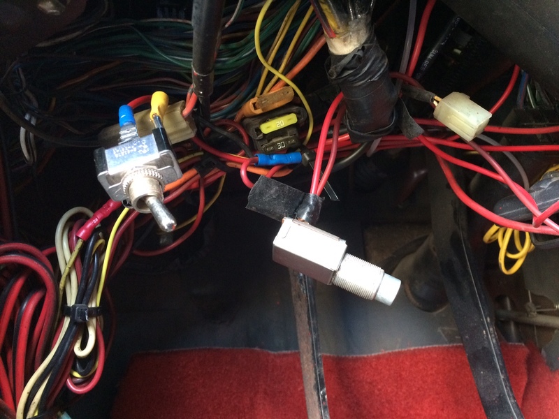
Here was the other half. Switch for the headlights and you can see the box for the tach on the floor in the background.
image7.jpg


Here was the engine bay as I uncovered everything and began trying to make sense of it. Tracing wires from the cabin to the bay alone was a complete pain in the ass. It took hours since every wire was red besides the 3 for the headlights (all yellow) and the routing was nonsensical.
image5.jpg


Here is a case of wiring where it took more effort to make it wrong. Wires around other wires.
image1.jpg


More wiring double dutch
image3.jpg


As you can see, I more than had my work cut out for me. After over 10 hours alone of messing with this I had a buddy I build cars with help me out to simply let me know what wire was moving in the bay when I pulled in the cabin. He was nice enough to stay and help me run a meter and further check everything out. We found quite a few wires that were loose on one end and also some that were zip tied into the mix and were connected to anything on either end. Once I got extraneous stuff out of the way and had help I was able to really fly through the wiring, or so I thought. We got to a point where everything worked besides the passenger side markers. We knew what color they were supposed to be so he ran the meter in the bay and I checked the passenger kick panel area.

Here is where I almost gave up on the project;


Uh oh, this don't look good. I assumed the rest of the harness would have been fine since all the previous splices/problems were on the drivers side and under the dash. You know what they say when you assume things...
image7.jpg


Once I unwrapped that I got a good idea of just how screwed I was. Every wire was cut and spliced and there was a clear meltdown with the headlight wires previously.
image8.jpg


image9.jpg


This was, BY FAR, the worst wiring I had ever seen. I was actually almost completely over it but I wasn't going to let a simple diesel swap and some rats nest wiring beat me. Lets fast forward an hour (after I put the hammer down and stepped away from the truck a while) Wipers are also stuck up because they didn't work and I was trying to figure those out as well when I took mental brakes from the wiring.
image2.jpg


A spare harness came with the truck so I went through that one with a fine tooth comb, found a few more issues, but was able to iron those out before I put it back in the car. Solder and heat shrink, no tape.
image5.jpg


While I was fitting the entire harness it was time to get this to run off the OEM key. I always thought it was odd the key was so smooth when unlocking the wheel so I took the column cover off and found that the ignition switch was just floating around in there. Well, time to figure out what the heck fastener it takes to fix this. The drill/tap/thread guide made this easy once I found the major diameter
image1.jpg


I then also noticed that there were more loose/cut and generally hacked at wires there. That made me glad I removed that cover, no point of leaving any stones unturned now. The top is how I remedy these problems. The bottom is how I found these.
image4.jpg


By this time I was making short work of all this. The harness was a million times easier to see and repair outside of the truck so once I had the replacement all buttoned up I gladly removed not only the one in the truck but almost every single wire dash/firewall forward. It was time to do it all the correct way. That meant an OEM harness, running from a OEM key, switching back to OEM gauges, and some type of headlight harness. Here we have how it looked after reinstalling everything.

Drivers side
image7.jpg


Passenger side
image6.jpg


Engine bay, not complete. Still messy and missing a few gauges to run the OEM dash properly.
image3.jpg
 
As briefly mentioned I was having some issues with the wipers not working. I searched the forum and found some info and the normal wiper arm bushing problem. I needed it fix asap so I figured I could whip something up using the lathe, a delrin drop, and a quick stop to McMaster. An hour later we had that fixed.

This could use a simple clean out and a clocking of the arm before I button it back up
image2.jpg


Put the good old Mori Seiki to use for this task. The 72" centers is a overkill for such a small part but in a time crunch you make it work
image3.jpg


Here is the broken part and the small temp fix
image5.jpg


Its not exactly the same as OEM but there was no way in hell I was taking measurements, writing a CAD program, and attempting to cut a similar piece out of this drop. Sometimes its just easier to recreate how a part works instead of an exact copy. the plastic piece is actually on the bottom of the pic instead of the face of the C clip. It lives right between the clip and wiper arm so it moves smoothly and should wear amazingly until I change it.
image6.jpg
 
In the process of all that the truck sat mostly in the same spot. I noticed that the oil leak I thought I either much more serious or leak(s), if not both. The new epoxy floor made it very clear.

image1.jpg


From the bay you could see that there was some seepage around the fittings on the hoses that had been covered with dust/debris but I figured it was previously addressed and just not wiped down well. Didn't seem like anything major but the floor told a different story.
image3.jpg


It was time to get under the thing and really look. With the lift it made it super easy. Not only could I just slide under it on a creeper but I had room to grab tools, move my arms, and generally work on whatever I needed. Here you can see there is oil in many places. Its hard to see but there is oil on the lower lines off the block and at the drain fitting (I will reference that more in detail later). The started and pan bolts are covered but that could have been just a logical path toward the rear of the drivetrain while driving.
image2.jpg


It was time to simply remove everything connected to the filter side of the system. I wasn't going to chase my tail with this especially not when I run stuff on my "street car" and bikes that I was positive would solve the issue.
image4.jpg

image6.jpg


Out with the old lines and fittings (and money from my wallet) and in with the Earls -AN fittings and Prolite 350 line. This stuff is absolutely great. Its super easy to use, and if you think a head and plumb a system using mostly straight fittings the cost is more than worth it. I wasn't so lucky this time as I decided to run the dual filter system in the current location until I am more sure what intake and AC/tensioning bracket I want to go with. It will more than likely be mounted low on the frame in the front of the bay so it will be easy to shorten the lines.
image7.jpg


Halfway done
image8.jpg


Here it is all done. Light years better in performance and aesthetics. The new turbo feed line is in there as well, I will detail that more later with the other side of the oil system that tried to fight me.
image9.jpg
 
The last part of the oiling system was the feed and drain to the turbo. It also turned out to be the biggest source of the leak and, quite frankly, the largest pain the ass. I actually found this first after coming across the thread the original owner posted showing the swapping of the motor and knew it would be a problem. The part Im referencing is the oil drain line. I wasn't fond of this goofy approach to a "simply" solution to routing the drain line for multiple different applications. The material seemed shoddy at best and upon further inspection after taking it off I wasn't wrong.


Here you can see the problem removed. This was about as bad as it could be. The drain from the center section is gravity fed back to the pan, or in the case of a 4BT there is a hole in the lower block that then flows into the pan. While the turbo wasn't starved of oil, blocking the return flow like this just keep hot oil in the center section of the turbo and potentially further back in the system. There were holes in a couple of sections from being flexed too much which actually helped at least give the oil a place to go. Anyway, I introduced this to the trash and looked up the weird fitting.
image2.jpg


The -10AN drain tube adapter wasn't hard to find online but at the time the shipping was more than the part. There was also some reason that weekend I needed to drive the truck and expediting the shipping would have been astronomical and letting it sit wasn't an option. Well... I guess I'll make it. Again, I didn't waste time trying to replicate the part I just took the critical dimensions and knocked it out.

image4.jpg


The flange is actually one complete piece of that pot metal bendy straw of an oil drain tube that was on there. I was hoping I would get lucky and be able to cut it off, clean it up, then weld it but it just became a mess as soon as I tried to strike and arc to tack it up. Well, looks like I'll make a flange from some scrap too. Ehhh... this was quickly getting annoying but it had to be done the same day.

AutoCAD the piece, go over the tool paths, the chuck the junk in the machine. First we chamfer the edges then mill it out. You can see the old flange and the one we made as well as the Earls AN weldable fitting I'm going to use for the oil drain side off the turbo.
image5.jpg


I got two of the Earls fitting to make both ends of the drain equation male ends and then return line can be a simple female end hose. Here are both, one after being faced in the lathe and cleaned vs right out of the package. Once that was done I used a punch to center the fitting on my flange to weld it out. Both sides done are shown in the lower left and right after you can see when I cut the damn thing back apart, hahaha. I knew the drain wasn't in the dead middle of the center but it was waaaay off. Next step as to cut it off, add a length to the part to clear the -AN fitting past the housing so it could be tightened down.

image6.jpg


Big lathes make you improvise when working with small parts
IMG_9638.jpg


I wish the material was better... or all stainless... but when dealing with time constraints and drops around the shop (see "free") you make what you have work.
image7.jpg


This was what I was talking about. This was tacked up just to see if my piece was long enough to clear the housing enough to throw a wrench on the fitting. Seems good so I weld it out.
image8.jpg


Here is the final comparison before installation. Much nicer and half the length
image10.jpg


Everything all said and done. Oil filter feed/return, turbo feed, and turbo drain all in place and buttoned up. I got rid of the hardline that fed the turbo, all the leaky lines, and now have a much better return in place and it looks like a million bucks. Freed up some room as well to start planning a different intake.
image1.jpg
 
Tools and skills, makes me feel like I don't even have thumbs! I see you are almost a masochist too,
might have been easier to build your own truck from scratch but thanks for the entertainment.
I'm all in now, J :popcorn:
 
Very nice work. I hate electrical work. Are you still looking for a gauge cluster? I have a nice gray OEM unit from an 87.
 
Exceptional work! You've got a great eye for finding solutions. Hope to hear this thing purring some day!
 
Wow, taking it to the next level here. Beautiful work machining those parts. Makes me want to buy more tools for my shop. "Honey...I'm buying a lathe! And a TIG welder!"


Cheers!
-Ed
 
Thanks for hanging in there and saving her. Mad skills!
 
It always seems to end with just ripping all wires apart and just label them one by one :wrench:
Good you had some help and fixed it with a second cable, is all the work to get it driving now finished?
 
Glad you got all that electrical trash torn out. Every time I looked at it I just cringed. I tried to get the courage a few times and was just overwhelmed.

The guy must have owned a 50000' spool of red wire.

Yeah, if I would have started with the worst case scenario I probably could have saved myself 16 hours or so. Fixing and replacing the entire harness took me roughly 4-5 BUT I now know FJ40 and FJ60 wiring like the back of my hand. Also, I know I can have a 4BT swap running using the stock harness with just a 1988 Ford Taurus starter solenoid, fuel solenoid, and a little bit of wire in half an hour.


Wow, taking it to the next level here. Beautiful work machining those parts. Makes me want to buy more tools for my shop. "Honey...I'm buying a lathe! And a TIG welder!"

Thank you. That's not a bad idea as I did exactly that. I will let you in on a little secret though. It's not the welder and lathe thats the problem... it's the vertical bandsaw, cold saw, grinder, air tools, and bridgeport that you tell yourself you need after thats the kick in the crotch.


It always seems to end with just ripping all wires apart and just label them one by one :wrench:
Good you had some help and fixed it with a second cable, is all the work to get it driving now finished?

It's been running for months. We didn't have a bad winter here and its back to being nice out so the truck just sits as I am back to riding motorcycles everyday. I'm actually considering selling it but thats something I will get to later.


Very nice work. I hate electrical work. Are you still looking for a gauge cluster? I have a nice gray OEM unit from an 87.

Thats for the offer but the stock one was included when I purchased the truck. I just dusted it off and put it back in.
 
Well since I did a ton of work in the last 6+ months and just never shared it I will keep this going.

This is about the hurdles I encountered while trying to get the stock gauges to work. First I got the cluster in and made sure things like the voltage and fuel level worked, which the did. The next step would be to get OEM (or similar) oil pressure and water temp sending units and then run those to the stock harness and hope they worked.

Step one was to remove the aftermarket sensor for the other gauges from the drivers side of the block. Only difficult part of that was that sensor had no flats machined on it to enable the use of a normal wrench. Ah well, par for the course. Once that was off I had to locate where it needed to reach in the harness, and of course it was all the way on the other side of the engine bay. So then I got a long braided line and the oil pressure sending unit and thought it would be smooth sailing. NOPE! I just happened to check the threads of this oil pressure unit and even though to the naked eye the outside diameter looked like 1/8" NPT it was BSP. Oh was I relieved and pissed at the same time. I'm just glad my industry has taught me to trust very few peoples work and absolutely NO ONE's measurements.

Here we are off the block
IMG_9349.jpg


So off I went on a journey to find hen's teeth. Really, I now needed a -4AN male to 1/8 BSP female fitting to work with my lines and the sending unit. That's one thing I never thought I would need, no less knew existed. Once I had everything in hand though it went right on and worked after I snugged up a small leak at a junction and it's worked flawlessly since.
image1.jpg


I'm was sure I had a pic of it in the engine bay all nice and neat in a fitting right under the wiper motor. I guess I will have to snap one and add it later.

After that things got really interesting trying to run the OEM temp sending unit on the 4BT. I had to search high and low for more parts I had no idea about. Not many places said they had the part and over half that said they did didn't have them in stock when contacted. The problem was the sending unit was 1/2NPT and the hole at the top of the 4BT was tapped M16. Once I had both parts in hand things just got dumber. Here is what I mean;


If you look down the center of this you can see 3 threads (there was maybe 1.25 more before we machined the chamfer in the throat, I'll explain why later). Why in the hell would make an adapter and not thread the center the entire way through when you clearly have the wall thickness to do so!?!? Also, when I called them and asked if this was a random flaw or if they all were like this they didn't get what the problem was or what I was saying. I guess the fact their listed dimensions only cover the outside thread length (see bottom of part in pic) wasn't helping the guy when I was standing in a machine shop giving him all the dimensions probably within .005"
image1.jpg


So because this is apparently the best the industry could do I have to machine everything else to fit. More annoyingly small parts in the lathe. Was unsure of how this was going to work out but the sending unit is cheap so if I scrap one it wouldn't be a huge deal. As you can see I had to turn off over half the threads.
image2.jpg


Here was a preliminary fitting. As you can see more threads needed to be turned off. Once we did that we needed to add that previously shown chamfer to have the o-ring seat and seal properly. This was all just flying by the seat of my pants by me and my buddy at work trying to get everything to work. All said and done it went in the first time with no leaks or problems.
image3.jpg


Here is the whole show finally in and working. Got the LEDs in as well. I will have to take a bay pic and show where these until live after all that work
IMG_9738.jpg
 
Very nice work.. great writeup.
 
Yeah, if I would have started with the worst case scenario I probably could have saved myself 16 hours or so. Fixing and replacing the entire harness took me roughly 4-5 BUT I now know FJ40 and FJ60 wiring like the back of my hand. Also, I know I can have a 4BT swap running using the stock harness with just a 1988 Ford Taurus starter solenoid, fuel solenoid, and a little bit of wire in half an hour.


J

16 hours... PHFFT!!! I would have shot myself in the head after a couple hours of that.... Your 16 would have been weeks, maybe longer for me. Even after getting the other harness and then looking at everything they had spliced, bypassed and re-routed made it even more of a challenge for me. You are more patient than I am and always nice to have a few buddies that know electrical. I asked a few guys on the forum and locals and the explanations were like Russian braille for me.

Good job.

J
 
I'm glad Goss is getting a new start! Jason did a TON of work to that rig and it shows. Nice to see the work continue!
 
NICELY Done, I wish I had your skills! What did you end up doing with the speed hut gauges?

I removed all the wiring, sending units, and gauges still in the custom panel and placed them neatly in a box. They are just sitting in the back of the truck now along with other parts I started to compile over the winter/spring.
 

Users who are viewing this thread

Back
Top Bottom