Dual battery systems and winches ... what to do about fuses? (1 Viewer)

This site may earn a commission from merchant affiliate
links, including eBay, Amazon, Skimlinks, and others.

CruiserTrash

Supporting Vendor
GOLD Star
Joined
Jul 15, 2020
Threads
60
Messages
2,365
Location
Denver
Website
cruisertrashparts.com
First time dipping my toe in the water of this part of the forum, and into dual battery systems in general. I'm going to be putting a dual battery system in my daily driver FJ60 in the coming months and I'm starting the process of designing the system and acquiring parts. I have a background in electronics repair and design, but it took me a bit to wrap my head around the lingo like DC-DC chargers, solenoids/isolators, MPPT, and a dozen other acronyms. I have a fair grasp on it now but I'm still not an expert. This build will be simple and budget friendly, and will probably undergo a major revision a few years down the road. The enemy of good is perfection, and while I'm a little OCD, I'm not going to let dreams of the perfect system stand in the way of installing a well-planned simple system now.

My question pertains specifically to incorporating a winch. I'm going to run two lead acid batteries (until the house battery dies and then maybe switch to a different type) with an isolator between them, and will put a fuse on on the cable from each battery to the isolator. It's safer that way and best practice. I may go with resettable breakers, but for now let's assume it'll be fuses. See this stolen photo:
screen-shot-2024-01-17-at-10-54-08-pm-png.3535898

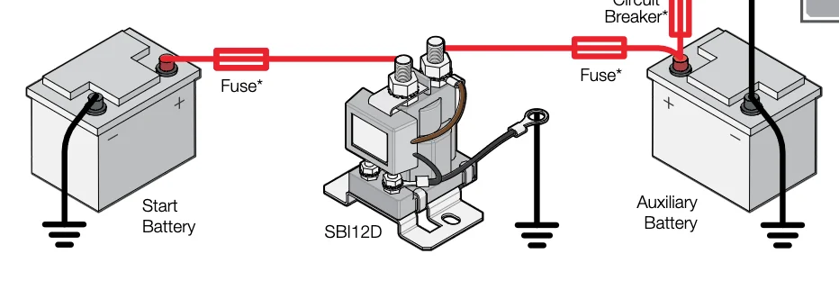
Now, when I go to use my winch, I'll increase the engine RPMs a bit, but I'd also like to run the batteries in parallel for this. They should already be in parallel anyway since the solenoid is energized and connecting the path between batteries. Here's the issue, however ... I'd like to have a fuse rated around 150A (derated to around 100-125A at engine bay temps), which is above my alternator output but below the rating of the 1/0 cable I'll be using. Plenty good to quickly catch a dead short if the insulation gets cut and the cable contacts the body. Let's say I'm stuck in some mud and in addition to the weight of the vehicle (4800lbs) there's additional resistance. My winch will supposedly draw 435A when it's at max capacity of 9500lb. According to the time constant graph on the Littelfuse datasheet, even at 300A of current draw and 60*F, the 150A fuses will blow in 1 second. Or one of them will anyway.

With my current single (starter) battery setup, the winch is wired directly to the battery with no fuses. I have an accurate voltage gauge in the cab that I watch and I monitor the temps of the winch and the cable while pulling. So how do I solve this issue with dual batteries? In practice are people just not making their winches work hard enough to blow the fuse(s)? Do I need second, fully manual isolator - essentially a big switch - in parallel to the first isolator so that I can bypass the fuses? Really, it would be taking the current draw on the house battery and splitting it in two down each cable, which would probably give the 150 fuse just enough headroom to not blow under most circumstances. So there would be current draw on the house main run, the house bypass run, starter battery, and the alternator - it might divvy up the load enough. That margin is a little thin for my liking though. Certainly this has been figured out, right?

Other things... I was initially leaning towards a Redarc SBI12D dual sensing isolator. The maximum current you can get on one of those is 200A. That also may not work for a winch. A friend recommended the BEP 720 marine isolator, also Aussie-made. It's also dual voltage sensing and has nearly identical characteristics to the Redarc unit, except it can handle 500A max. The house battery is going to be running some interior LED lighting, chargers, GMRS radio, and a fridge. Pretty basic. I may add an MPPT and a solar panel down the road. Monitoring will be done with two simple voltmeters in the cab, one off each battery. I'm going to add a manual override switch in the cab - both isolators are capable of that - in case the starter battery is dead, so I can start off the house battery. I'm interested in hearing about different "self jump" systems though, especially if I eventually move to a deep cycle AGM battery for the house. That is a must for us though, probably the #1 reason I'm going to all this trouble. A dead starter battery after a few days in the backcountry is a bad situation to be in. We've been there and luckily got some help and were able to get moving.

So, I wrote y'all a novel-length explanation. What do you think about my winch question?

Screen Shot 2024-01-17 at 10.54.08 PM.png
 
I put a Blue Sea Systems ACR or BEP Marine VSR in parallel with a Blue Sea Systems Marine Battery Bank Switch in my dual battery systems. Wires connecting the two are short because the two units are always mounted right next to each other. That gives me a manual switch to combine the batteries for any number of reasons. I can also change which is the starting battery.

On the Snowball/Blanc-oh! project I did exactly what gnob suggests, the winch is on a battery kill switch located right next to the battery bank switch. I thought that I had a pic of this, but I do not.
 
So essentially an unfused, switched, positive run bypassing the solenoid? Like this diagram? Note the fuses (sine wave looking things between the batteries and the solenoid) and the switch (above the solenoid). I’m used to drawing in schematics language, apologies if that‘s not typically how dual battery setups are illustrated.
A5D0A21A-E433-40C8-AFFF-F09771AA1282.jpeg
 
Schematically that's close to what I have between the batteries, but physically it is a bit different. The marine battery bank switch has three terminals, BattA, BattB, and Load. My ACR/VSR is connected to the BattA and BattB studs with a total of about 10" of 10 ga. 1/0 to each battery. Both batteries grounded via 1/0 to the same bolt. Any load fusing, breakers, or fusible links are connected to the Load terminal on the battery bank switch in the engine bay. The house battery sits some distance away and has it's own loads that are fed by a 285 series breaker bolted next to it.

Then the winch "arming" switch draws power off the Load stud of the banks switch. As it sits right next to the battery banks switch the 1/0 power jumper between the switches is maybe 8" long.
 
Schematically that's close to what I have between the batteries, but physically it is a bit different. The marine battery bank switch has three terminals, BattA, BattB, and Load. My ACR/VSR is connected to the BattA and BattB studs with a total of about 10" of 10 ga.
What is “ACR/VSR”? The marine battery bank switch is similar to what I’m using the solenoid for in my diagram? And the load contact is a sidechain input that can override the normal isolate/combine functionality of your marine battery bank seitch?

1/0 to each battery. Both batteries grounded via 1/0 to the same bolt.
I plan on a common ground point for both batteries to minimize floating ground/potential difference/noise on the B+ rail. 1/0 cable for the grounds as well as the battery-solenoid-battery cables. Engineering the fuses to be the failure point in other words - not the cables. All winch-related cabling will be 1/0 as well.

Any load fusing, breakers, or fusible links are connected to the Load terminal on the battery bank switch in the engine bay. The house battery sits some distance away and has it's own loads that are fed by a 285 series breaker bolted next to it.
I know I spoke a lot about fuses above but I’m likely going to use breakers of 100-150A from each battery’s positive post to the solenoid. Ignoring the winch, that should give me a tighter safety factor without nuisance breaker popping.

Then the winch "arming" switch draws power off the Load stud of the banks switch. As it sits right next to the battery banks switch the 1/0 power jumper between the switches is maybe 8" long.
The rest of what you said lost me. I think I’d need to see a schematic. I did pick up some
Bits from this though, thanks.
 
ANL fuses go a bit higher than 300A, pricey though


Something like that for short circuit protection + a switch/disco would be my choice
I would like to keep the fuses or breakers between the batteries and the solenoid lower than that. My alternator puts out less than 100A at full tilt, and with every current draw widget going in the truck I should be well under 100. I like having fuses sized tight, but not so tight they blow on inrush current from turning a device on. 100-150A is my rough estimate right now before I sit down and add it all up. That’s pointing at Mega fuses for my purposes.

ANL is something to think about if I do want to actually fuse the winch. I haven’t really looked into them, but I do use Mouser all the time so I’ll comb through and have a look at some datasheets.
 
Use what the EV OEM's are using: GigaFuse | Sensata Technologies - https://www.sensata.com/products/gigavac-power-contactors-fuses/gigafuse Well, maybe not. $$$$

I've also seen a array of breakers in parallel used to achieve an amperage greater than any single breaker is available for. Never done it, I get the impression that doing so isn't as straight forward as it might seem. I've elected not to worry about it. Being able to turn off the battery(ies) with a switch is good enough.
Whoa, GIGA fuses, now there’s a concept! Going back to what I said previously, I want to get the fuses relatively tight to the current flow that the system will see. Let’s say 100A charge or draw is the most I’d ever see. If I have a 400A fuse and I get a dead short somewhere, that big honkin’ fuse will have a much longer reaction time than a 150A fuse.
 
It isn't common in light duty vehicles to fuse the really heavy loads. At least partly because of the lack of the components to do so, but also because of the expense of those components that are available. I don't worry about the starter motor or winch motor loads. Everything that I add to a vehicle excepting a winch is ultimately on a 285 series breaker or sometimes a fusible link. Only I make the fusible links so that they screw to a terminal strip and I make up a couple spares to carry with me. Makes fixing a burnt one really easy that way.

Perhaps one way to handle any potential very high current short pro-actively would be to put a battery kill switch in the system. With two batteries I would put it in the circuit between where the battery grounds become common (use one stud on the switch itself for this?) and the actual grounding to the chassis. Hella makes one that will carry 1000A for a short time.
Whoa, GIGA fuses, now there’s a concept! Going back to what I said previously, I want to get the fuses relatively tight to the current flow that the system will see. Let’s say 100A charge or draw is the most I’d ever see. If I have a 400A fuse and I get a dead short somewhere, that big honkin’ fuse will have a much longer reaction time than a 150A fuse.
Nothing friable in those fuses, nothing melts or burns. Not sure how much I can say about how they work w/o getting into trouble.
 
It isn't common in light duty vehicles to fuse the really heavy loads. At least partly because of the lack of the components to do so, but also because of the expense of those components that are available. I don't worry about the starter motor or winch motor loads.
That’s the same assumption I’m under, and what I’ll be doing. That’s why I’m trying to figuring out an alternate path for the winch or switching: normal operation sees the batteries isolated or combined by the solenoid with fuse/breaker protection on the positive cables. Starter will have already has an unfused 1/0 cable from the starter battery, that won’t change, and the solenoid will isolate the batteries during starting. The starter will not be drawing current from the second battery through the fused positive cables. The winch I would like BOTH batteries combined, but NOT fused.

My options are looking like a manual bypass switch bypassing the fuses and solenoid, or perhaps I can wire a relay to the solenoid override wire. I was going to use that to install an override switch in the cab to control the solenoid anyway, but I could make that switch also trigger a relay that operates the second switch for the bypass path. Hmmm.

Everything that I add to a vehicle excepting a winch is ultimately on a 285 series breaker or sometimes a fusible link. Only I make the fusible links so that they screw to a terminal strip and I make up a couple spares to carry with me. Makes fixing a burnt one really easy that way.
I’ve made a plug & play kit for 60s to replace the fusible link with MIDI fuses, I’ll continue to run that off the starter battery for the normal truck electrics. Keep the stock system intact. Given an equal rating MIDI fuses have just about the same opening time as fusible link wire of about 6” length, and maybe a touch faster. That’s inferring and doing the best I can to ascribe a value to different gauges of fuse link wire - it’s a rough comparison.

The rest of the additional components will be protected with with a combination of breakers, and MIDI and ATC fuses.

Perhaps one way to handle any potential very high current short pro-actively would be to put a battery kill switch in the system. With two batteries I would put it in the circuit between where the battery grounds become common (use one stud on the switch itself for this?) and the actual grounding to the chassis. Hella makes one that will carry 1000A for a short time.
Why install another switch when you can use a resettable breaker or fuse of the appropriate size for the system? The switch might react faster, but the fuse or breaker in the sizes I’m looking at are going to have a reaction time of less than 1 second in that extreme of a circumstance.

Nothing friable in those fuses, nothing melts or burns. Not sure how much I can say about how they work w/o getting into trouble.
Got the inside info on GIGA fuses I see! 🤔
 
I use the battery bank switch / ACR combo to keep the batteries isolated when starting unless I deliberately switch to "Both" in a self jump-start situation or to use the winch. I do have to open the hood to make that change, but I see that as a good thing because it won't get done accidentally.

I was thinking of the kill switch as being a "manual fuse" instead of some big honkin' fuses in the high current cables. Only reason for it to exist is to be manually turned off in the event of a catastrophe.

Let's just say that I've seen and heard those giga fuses being tested when they were being first developed. At those VDC-A levels they make a noise!
 
This is entirely too complicated.
Look at your batteries for their max discharge rate. May be surprising.

I recommend (as it's how mine are wired and has worked in loaded situations before), looking at your purple sticky...put a dash-switched 200A relay where that "can/cylinder" is.
Then also wire the winch + to one batt + and winch - to the other batt -.
Fusing as you have it stays the same.
This will give the winch one batt to work with all the time. If you want both batts, flip the relay switch and there you go.
Mine has worked fine going on 3 yrs+. My winch is 10K and longest pulls were with heavy trucks uphill for more than 1 minute (yeah not recommended).
The relay rating of 200A is one limiter, but the winch wiring (2ga, which is too small) is actually on 100A MRBF fuses and it's still had no issues with current draw over that time.

Worst case, up the fuses if they blow. But I'll bet the 200A relay will have no issues.
Unless of course I'm missing something and that's possible as the threads were indeed novels. lol
:cheers:
 
Last edited:
I’d go with the same layout as redarc shows for their smart relay but with the added fuses on either end of the positive batteries like you’ve suggested before. But instead of the redarc relay use the Blue Sea ML-ACR 7622. It’s got a much better amp rating of 500 amps continuous and 1450 amps for 30 seconds (assuming your wiring and fuses could handle that). It can still automatically open and close the relay based on voltage so you can’t run down both batteries. You can force it to close the relay for situations like self jump starting or winching. It’s basically offering good automatic and manual control of how the relay operates with no need to open the hood.

It’s also rated for marine uses. Which is a plus.
 
I prefer a manual switch for the "self jump-start" mode. What happens if the battery that I need to jump is the one that the contactor draws its operating power from? Which means opening the hood. That doesn't bother me, I want to be very deliberate about operating that switch.
Since I have the winch on a manual marine on-off switch, and it sits right next to the marine battery combiner switch I'll need to open the hood to winch anyway (winching safety used to instruct that with a front mounted winch that the hood be open anyway), so pairing the batteries for that use isn't significantly different than just turning on the winch.
Using an ACR or VSR for charging simplifies the wiring and the install.
I'm not a fan of high current fuses. When I can I keep the unfused high current cables short or switched off, and when I can't I make sure that they're well protected.

That is just how I prefer to have things operate. Everyone has their own preferences, and those are correct for them.
How I approach any proposed system is "How do I want it to operate?" Then I go looking for the components that will make it operate that way. Looking at the range of what is possible is too bewildering.

I did look up the 5 second discharge rate, it is 1500 amps for the Odyssey Group 65 in Snowball. Clearly I'm not going to cable the vehicle for that, just for the max load or the least Voltage Drop depending on which is more important to the circuits in question. I could not find that spec for the Optima 34/78 in the Wagon.
 

Users who are viewing this thread

Back
Top Bottom