Well this was interesting. I hope you don't consider this a hijack.
For the record, headlamps in a 40 series are 75W ea. - so you should see 12.5A of discharge on the gauge when the engine is off. If you don't then something is wrong.
Luckily I maintain a supply of finely tuned instruments for such experimentation - I store them carefully under controlled conditions to ensure like-new operation.


So test #1, I checked to see what voltages my own ammeter takes in order to swing the needle. I was shocked, however, like Tom mine took roughly 300mV to swing to 50A (voltage is on the right hand meter):
You can see actually that 300mV was a little over the limit for me, I think 50A was about 250mV on my gauge. Of course without an extra digit on my display thats all guesswork.
So thats two datapoints in favor of ~300mV. Hmmm.
For the next test I checked to make sure I was correct about the length of the shunt. I found some plain copper wire, in 14ga:
And wired up 18" of it to my power supply. I switched to constant current mode and attached the ammeter across the wire. Here is a shot with an 18" 14ga shunt at 15.0A:
Just to be extra certain I also hooked up 100" of 14 ga. wire to act as a load, with 4 taps every 6" so I could vary the length of my shunt:
The results with a 12" shunt (25A shown):
18" shunt:
And lastly a 24" shunt:
Now you may be thinking "but Drew, maybe the OEM fusible link was made out of a material other than copper, and therefore could be shorter!"... and you'd be correct. Based on these results, you could make an equivalent shunt with 4.5" of 14ga. nickel wire, 2" of steel, or 1/4" of nichrome, etc etc.
But...
a) the OEM link LOOKs like copper (see Tom's pics from the other thread). There aren't a lot of other orange metals, so whatever the OEM link was made out of, it at least had a lot of copper in the alloy... and that means that the resistance isn't TOO far different than copper wire. Tom's pic:
And more importantly...
b) If the OEM shunt becomes damaged the resistance will increase - this will have the effect of INCREASING the action of the meter, as Tom saw in the days before his shunt failed. However there is no mechanism by which damage/aging/magic can DECREASE the resistance of the link... So we have no explanation for why good ammeters on intact OEM shunts still don't work after you check their fuses.
... or do we?
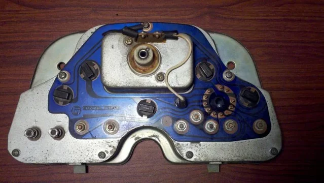
I think the gauges themselves are getting old. Some notes on the gauge construction. The wires from the shunt attach to this coil on the back of the gauge:
On the other side of the gauge, this barbell shaped piece of metal is attached to the needle:
The two black squares you see sticking out "over" the barbell, next to the screws at the lower corners of the gauge, are the ends of a permanent magnet.
Note that the barbell itself is magnetic, you can see it here attracting itself to a nearby drillbit:
Therefore:
- I think that the OEM fusible link was indeed 14ga. copper or mostly-copper, however as it was clearly not 18" long there must be some other issue at work here.
- I think that over time, the barbell becomes magnetized as well as the horseshoe magnet weakens and this affects the operation ot the gauge.
- I think there is a certain "ground state" that the magnet components of the gauge eventually reach, which is why Tom and I see the same readings.
- I also think that, during fault situations (shorts, blown fuses, etc) the gauge sustains a high current pulse which has the affect of further demagnetizing the horseshoe and or barbell.
QED.


 , interesting, food for thought, I need another break, more coffee please, dear


