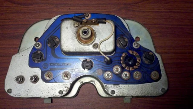
Clusters, Gauges, Speedo & Odo meters (5 Viewers)

This site may earn a commission from merchant affiliate
links, including eBay, Amazon, Skimlinks, and others.

Back again, there is no more coffee.
Let's stick to the 10Amp draw by the headlights.
10Amps draw over a 6 milliohm resistor makes 60mV voltage drop, which is 1/5 of 300mV, which is 10Amps on a 50Amps scale. Good, this circle is closed.
But...... we calculated, and therefore assumed, that the resistance of the Fusible Link is 0.006 ohm but we have no proof of that. If I take in the numbers of Tom (10mV when the headlights are on and 20mV with the fan and Ignition on) I come to the conclusion that the R value of the Fusible Link is mucho much less then the calculated 6 milliohm.

I have to go back to the books and tables about wire sizes, resistance, amps, et cetera to get some things clear.

To be continued.

Rudi
 
Well this was interesting. I hope you don't consider this a hijack.

For the record, headlamps in a 40 series are 75W ea. - so you should see 12.5A of discharge on the gauge when the engine is off. If you don't then something is wrong.

Luckily I maintain a supply of finely tuned instruments for such experimentation - I store them carefully under controlled conditions to ensure like-new operation. :D:D
1-600.jpg


So test #1, I checked to see what voltages my own ammeter takes in order to swing the needle. I was shocked, however, like Tom mine took roughly 300mV to swing to 50A (voltage is on the right hand meter):

2-600.jpg

3-600.jpg

4-600.jpg


You can see actually that 300mV was a little over the limit for me, I think 50A was about 250mV on my gauge. Of course without an extra digit on my display thats all guesswork.

So thats two datapoints in favor of ~300mV. Hmmm.

For the next test I checked to make sure I was correct about the length of the shunt. I found some plain copper wire, in 14ga:

5-600.jpg


And wired up 18" of it to my power supply. I switched to constant current mode and attached the ammeter across the wire. Here is a shot with an 18" 14ga shunt at 15.0A:

6-600.jpg


Just to be extra certain I also hooked up 100" of 14 ga. wire to act as a load, with 4 taps every 6" so I could vary the length of my shunt:

7-600.jpg


The results with a 12" shunt (25A shown):
8-600.jpg

9-600.jpg


18" shunt:
10-600.jpg

11-600.jpg


And lastly a 24" shunt:
12-600.jpg


Now you may be thinking "but Drew, maybe the OEM fusible link was made out of a material other than copper, and therefore could be shorter!"... and you'd be correct. Based on these results, you could make an equivalent shunt with 4.5" of 14ga. nickel wire, 2" of steel, or 1/4" of nichrome, etc etc.

But...

a) the OEM link LOOKs like copper (see Tom's pics from the other thread). There aren't a lot of other orange metals, so whatever the OEM link was made out of, it at least had a lot of copper in the alloy... and that means that the resistance isn't TOO far different than copper wire. Tom's pic:

And more importantly...

b) If the OEM shunt becomes damaged the resistance will increase - this will have the effect of INCREASING the action of the meter, as Tom saw in the days before his shunt failed. However there is no mechanism by which damage/aging/magic can DECREASE the resistance of the link... So we have no explanation for why good ammeters on intact OEM shunts still don't work after you check their fuses.

... or do we?

I think the gauges themselves are getting old. Some notes on the gauge construction. The wires from the shunt attach to this coil on the back of the gauge:

14-600.jpg


On the other side of the gauge, this barbell shaped piece of metal is attached to the needle:

16-600.jpg


The two black squares you see sticking out "over" the barbell, next to the screws at the lower corners of the gauge, are the ends of a permanent magnet.

Note that the barbell itself is magnetic, you can see it here attracting itself to a nearby drillbit:

13-600.jpg


Therefore:

  • I think that the OEM fusible link was indeed 14ga. copper or mostly-copper, however as it was clearly not 18" long there must be some other issue at work here.
  • I think that over time, the barbell becomes magnetized as well as the horseshoe magnet weakens and this affects the operation ot the gauge.
  • I think there is a certain "ground state" that the magnet components of the gauge eventually reach, which is why Tom and I see the same readings.
  • I also think that, during fault situations (shorts, blown fuses, etc) the gauge sustains a high current pulse which has the affect of further demagnetizing the horseshoe and or barbell.

QED. :D
 
Last edited:
Let me add one more:

  • I also believe that a longer shunt is an acceptable solution to "old ammeter" symptoms. The extra resistance is not large enough to be a concern.
 
Whoopeee!

Rudi's done a good job in getting you enthused enough to get out your gear and start experimenting with us Drew.

But I'm not sure about your "magnetism/demagnetism theory".

When I first bought my cruiser it was only 2 years old and the ammeter was a lazy sod back then too. - So surely 2 years is too short for the ammeter to deteriorate in this way.

And I agree that a fusible link is more robust as a long length of thicker wire than as a short length of thinner wire (because then it is less likely to undergo significant deterioration from strand breakages or corrosion). But I think Toyota had to choose "short" because it wanted all fusible links to be able to be easily changed in the event of failure.

With a long length I don't think it would be advisable to coil it (because that would tend to overheat the link and encourage arcing at switches) and neither would it be advisable to run it within the loom like the rest of the wires (because then it could burn other wires if it blew and it couldn't easily be changed).

So I think they were forced into "short-length" and then upped the thickness at the last minute for fear of the link breaking or deteriorating rapidly.

Anyway, I think I'll stick with my ammeter as it is now because it does at least serve two purposes:
  • It backs up my arrow-lights on my combination meter (and the clicking noise coming from my relay) by "twitching" to tell me I've left my indicators on, and
  • It starts to move away from zero with a little more determination to alert me whenever my fusible link is damaged
:D

PS. And of course I now have my aftermarket voltmeter to tell me if my battery is being charged or drained.
 
Hi Drew,

Amazing job you did, chapeau!:clap:
Do I see it right that the current in this pic is 1.1Amp?
4-600.jpg

That means that this gauge is not a mV meter, as I assumed, but an internal shunt amp meter. Right?
Which runs parallel to the Fusible Link. Right?
So the new diagram looks like this;
ammeter diagram 79 later.JPG

Which translates to: 50 Amps through the Fusible Link is equal to 1Amp through the AMP meter.
Or; 98% of the current runs through the FL and 2% through the ammeter.

:hmm:, interesting, food for thought, I need another break, more coffee please, dear :princess:

Rudi
 
Last edited:
Ammeters have a low internal resistance, say 1 or at most a few ohms. While (milli-) voltmeters have a relatively high internal resistance, say a thousand ohms or more. So you can determine what this gauge is by just measuring its internal resistance.

The wiring diagrams in post #75 and #85 are identical. The only difference is how you are thinking about it.
 
Ammeters have a low internal resistance, say 1 or at most a few ohms. While (milli-) voltmeters have a relatively high internal resistance, say a thousand ohms or more. So you can determine what this gauge is by just measuring its internal resistance.
The wiring diagrams in post #75 and #85 are identical. The only difference is how you are thinking about it.

Agreed.

And accordingly, "ammeter" is the most accurate description of the early-type 40-series device (where all the charge/discharge current passes through the meter terminals) while "millivoltmeter callibrated in current-units" is the best description of the latter-type that has the fusible link as a shunt (where just a milliamp-sample-current passes through).

:cheers:

PS. And I don't think 1.1A could be flowing through the Toyoto millivoltmeter in Drew's pic Rudi. Edit: Oops. If you read Drew's reply down below the ammeter does draw 1.1A to read 50A! I think it is instead flowing through a "test shunt". (But as usual, he got in so deep he may have lost me in some places because of my "limited attention span".)
 
Last edited:
The wiring diagrams in post #75 and #85 are identical. The only difference is how you are thinking about it.

Hi TrickyT,

I understand what you're saying. The point is: If you look for the first time at a or this diagram, what do you think? Is it a Volt meter or an Amp meter?

When (long, long time ago) I was working on complex systems, with a lot of gauges, the circuit diagrams had these symbols (see below) so you didn't have to figure out what a gauge was for, tracing back the wiring. It was immediately clear what it's purpose was. With this engraved in the back of my head and not having this particular gauge in my hands and looking at the Toyota diagram I'm still wondering..... what type of gauge is it?
meter soorten.JPG

I'll think we have to wait for Drew to tell us what type it is.

EDIT: If it's a Volt meter you don't need 5Amp fuses for protection. 100mA will be good enough. This gives me the idea that it's an ampmeter which deflects full scale at 1 Amp.


Rudi

meter soorten.JPG
 
Last edited:
...EDIT: If it's a Volt meter you don't need 5Amp fuses for protection. 100mA will be good enough. This gives me the idea that it's an ammeter which deflects full scale at 1 Amp...

That's my thinking too. The windings you see on the back of the late '79 gauge shown in post #82 are not what you'd see on a high-impedance voltmeter, especially one that needs to swing full scale with only 300mv input. For that you'd need a meter with a lot of windings of very fine wire. Also, ammeter shunts are typically calibrated devices because the voltage drop across them is small, especially at small currents, but needs to accurately track the current. That also makes them relatively expensive. But fusible links aren't like that; they're both cheap and made to be replaced. So it makes a lot of sense for the gauge to indeed be an ammeter and measure current, but to only measure a portion of the total current with the majority of it going through the fusible link.
 
Whoa, you guys are confusing yourselves. There is ZERO utility in deciding what to call this gauge.

Ammeters and voltmeters are the same instrument - its properly called a galvanometer. All of these gauges measure voltage, amperage, magnetic field, wattage, etc all at the same time - the only thing that matters is what the markings on the gauge have been calibrated to show, everything else is relative.

For example, an internal shunt ammeter displays the current flowing through the shunt inside it. That is equivalent to saying that it measures the voltage drop across the posts of the gauge. Its also equivalent to saying it measures the magnetic field produced by the current in the shunt. And it is ALSO equivalent to saying it measures the power dissipated in the shunt. The designers of the gauge just choose which of those things are important and print the scale on the face of the gauge with instructions how to hook it up.

To Rudi/Tom's question - my first photos show the gauge hooked up without any shunt... i.e. I'm powering it like a voltmeter. And indeed it works fine as a voltmeter, though it pulls a lot of current. We can use that measurement to determine that the meter has an internal resistance of about .27ohms.

... if I was to generalize voltmeters, most (but not all!!) have resistances on the other of 100's of kiloohms, or megaohms. This is because that is how the gauges are most useable, not because its a requirement for them to be a voltmeter.

... likewise I'd say that ammeters generally have resistances well below 0.1 or even 0.01 ohms... again not because they have to, but just because thats how they're most convenient to apply.

Therefore this gauge lives in an odd "middle ground" between traditional ammeters and voltmeters. I was surprised it pulled as much current as it did, but I guess thats how Toyota wanted it.

To summarize:

  • Yes, 1.1A does indeed flow through the gauge when the indicator is reading 50A
  • You can call the gauge whatever you like, it makes no difference - the needle deflection is proportional to the magnetic field in the gauge, which is proportional to the current through the gauge, which is proportional to the voltage across the gauge, which is equal to the voltage across the external shunt, which is proportional to the current through the shunt. Its ALL THE SAME!
  • The fuses are definitely required - the meter in my pics actually had a blown coil from too much current going through it. That tiny coil wire is safe at 1.1A, but over a couple of A it will blow... thus why this is used with an external shunt, and why its protected by 2.5A fuses.
  • Tricky is right when he says the shunt is critical... which is why its frustrating that the fusible links are being used as the shunt. But the design of the gauge in no way compensates for this - its nothing special, its only as good as the shunt you provide it.
 
...
... if I was to generalize voltmeters, most (but not all!!) have resistances on the other of 100's of kiloohms, or megaohms. This is because that is how the gauges are most useable, not because its a requirement for them to be a voltmeter.

... likewise I'd say that ammeters generally have resistances well below 0.1 or even 0.01 ohms... again not because they have to, but just because thats how they're most convenient to apply...

The other reason that you want voltmeters to have a very high internal resistance and ammeters to have a very low internal resistance is that you don't want the meter to have an affect on the circuit you are trying to measure. Otherwise just connecting the meter to the circuit may change the operation of that circuit. This isn't a critical factor in low tech circuits like auto electrics, but it definitely is in general electronics.

...The fuses are definitely required - the meter in my pics actually had a blown coil from too much current going through it...

Also, if the fusible link breaks or melts, the ammeter fuses will prevent the full current from the battery and alternator from going through the ammeter which, it appears, is only designed for ~1.1A.
 
Hi Drew,

Thanks for the extensive research and explanation on meters and gauges and providing all the answers to our questions.

Now back to this thread about how the ammeter in the '79 and later series works.
The AMP gauge runs parallel to the Fusible Link and measures the current at a ratio of 50:1 as shown in this pic.
ammeter diagram '79 and later + text.JPG

The two 5Amp fuses are protecting the ammeter circuit in case the Fusible Link blows and protect the wiring from burning in case of chafing (to ground) or a short in the ammeter circuit.

Now the only question remaining is: Why doesn't the AMP meter reflect the current going through the Fusible Link?

Putting everything together it's my opinion (and not only mine) that there is a design flaw pointing in the direction of the Fusible Link.
Either the Fusible Link needs to be a smaller wire size or must be longer. For one or some reason Toyota let this one slip the production?

If somebody has a different idea, please post up here.

Rudi

ammeter diagram '79 and later + text.JPG
 
Last edited:
Great thread !

Way...way over my head. But great info to have & be able to refer to. Keep up the good work.

John
 
The AMP gauge runs parallel to the Fusible Link and measures the current at a ratio of 50:1 as shown in this pic.
View attachment 604379

Assuming that we have faith that our old ammeters are operating as designed, then yes, the proper current ratio is 50:1.

Now the only question remaining is: Why doesn't the AMP meter reflect the current going through the Fusible Link?

Putting everything together it's my opinion (and not only mine) that there is a design flaw pointing in the direction of the Fusible Link.
Either the Fusible Link needs to be a smaller wire size or must be longer. For one or some reason Toyota let this one slip the production?

Choosing between a monumental screwup by Toyota or a mysterious aging phenomenon in the ammeters themselves, I believe the aging effect is the more likely of the two. Of course thats open for debate. Tom's recollection of his ammeter when new is a datapoint against my aging hypothesis, but I'm not sure its definitive unless he tried to test it out specifically back in the day.
 
Hi Drew,

Thanks for the extensive research and explanation on meters and gauges and providing all the answers to our questions.

Now back to this thread about how the ammeter in the '79 and later series works.
The AMP gauge runs parallel to the Fusible Link and measures the current at a ratio of 50:1 as shown in this pic.
View attachment 604379
The two 5Amp fuses are protecting the ammeter circuit in case the Fusible Link blows and protect the wiring from burning in case of chafing (to ground) or a short in the ammeter circuit.

Now the only question remaining is: Why doesn't the AMP meter reflect the current going through the Fusible Link?

Putting everything together it's my opinion (and not only mine) that there is a design flaw pointing in the direction of the Fusible Link.
Either the Fusible Link needs to be a smaller wire size or must be longer. For one or some reason Toyota let this one slip the production?

If somebody has a different idea, please post up here.

Rudi

Here's one theory of what's going wrong:

As you point out, the design calls for a ratio of 50:1 for current passing through the fusible link compared to that passing through the ammeter, if the ammeter is to read total amps accurately. The problem with this design is that it depends critically on the exact ratio of the resistance of the fusible link and the internal resistance of the ammeter, since it is this resistance ratio that determines how the flow of current "splits" between the two parts of the circuit. This ratio of resistance must be exactly 50:1 for the current ratio to also be 50:1. If one of the resistances changes, the ratio of current flow will no longer be 50:1 and the ammeter readings will be inaccurate. This 50:1 ratio is exacerbated by the fact that the resistances are so small to begin with --- meaning you are depending on the ratios of small numbers for ammeter accuracy, which is just not a good design.

To provide some concrete numbers, assume that the resistance of the fusible link is 0.005 ohms and the internal resistance of the ammeter is 0.25 ohms, a 50:1 ratio. What if the fusible link ages and it's resistance goes up to 0.006 ohms? Without a special measurement setup like a Whetstone bridge, you couldn't reliably measure such a small change in resistance, not even with an expensive with 3 1/2 digit digital multimeter, and yet the resistance ratio has now changed to .006/.25 = 41.6. In other words, if the alternator was pumping out a hefty 50A, the ammeter now would only be reading slightly over 40 amps. So a huge change in reading for only a tiny 0.001 ohm increase in resistance.

Another way to look at it: any increase in resistance of the fusible link is multiplied by 50x in the meter reading.

To make matters worse, analog meters are least accurate at the low end of their ranges. So in Amaurer's headlight example of 12.5A current draw with the headlights on, the meter is only going to move about a needle's width off the center 0 reading under ideal circumstances, and even less if there's any increased friction in the meter bearings because of dust or the resistance of the fusible link has gone up a little. All of this points to the downside of trying to accurately measure current using a shunt. To do it right you need a shunt whose resistance is very accurately known and that doesn't change with age or heat. Does that sound like the properties of an inexpensive fusible link made using 30 year-old technology? Sure, the fusible link is just ~6" of copper wire, but it's purity and size must be accurately controlled if its resistance value is to be depended on for an accurate ampere measurement.
 
I don't believe a piece of copper wire will change resistance much over 25 years. The connectors, on the other hand, definitely will, as will the magnet in the gauge (I know, I'm harping on that magnet...). The bottom line is the same - the fusible-link-as-shunt concept is crap. For example here is a picture of what a proper shunt should look like:

8255.jpg
 
So does this mean that the only difference between the 12 Volt and the 24 Volt panels is the "dropper" installed in the back???
 
Hi Tobash,

The dropper, the OIL gauge and the 5 light bulbs are different between a 12V and a 24V cluster.
The full explanation is in posting #24.

Rudi
 
....Ammeters and voltmeters are the same instrument - its properly called a galvanometer. All of these gauges measure voltage, amperage, magnetic field, wattage, etc all at the same time - the only thing that matters is what the markings on the gauge have been calibrated to show, everything else is relative. .......

Quite right Drew. We were just arguing about "common terminology".

But it sure can be enjoyable to argue :D

I'm powering it like a voltmeter. And indeed it works fine as a voltmeter, though it pulls a lot of current. We can use that measurement to determine that the meter has an internal resistance of about .27ohms.

Thanks for doing your tests Drew. We've gained a lot of headway from those.

I found 0.3V is needed across my fusible link to get a full-scale needle-deflection (50 ampere reading) on my "ammeter" and you found your ammeter drew 1.1A under those conditions.

And Mr Ohm says V= I x R and 0.3 = 1.1 x 0.27 so we're all good there.

But honestly that high current and low resistance surprise me.

That tiny coil wire is safe at 1.1A, but over a couple of A it will blow... thus why this is used with an external shunt, and why its protected by 2.5A fuses.

Those fuses are 5 amp rating Drew so hopefully our ammeters can withstand 5 amperes:
Ammeterfuses2.jpg


... if I was to generalize voltmeters, most (but not all!!) have resistances on the other of 100's of kiloohms, or megaohms.

The other reason that you want voltmeters to have a very high internal resistance and ammeters to have a very low internal resistance is that you don't want the meter to have an affect on the circuit you are trying to measure. Otherwise just connecting the meter to the circuit may change the operation of that circuit. This isn't a critical factor in low tech circuits like auto electrics, but it definitely is in general electronics.......

I think this is important.

Only 0.3V (or 300 millivolts) drives the meter to a full-scale (50 amp) needle-deflection yet the meter draws 1.1A.

So 1.1 A is flowing through the meter and bypassing the fusible link.

I think this meter DOES affect the circuit it is "testing" then.

If you think of it as a millivoltmeter (and sorry to revert to that), then I think when it's drawing 1.1A it will be lowering the voltage drop across the fusible link.

In other words, if you were to disconnect the ammeter/millivoltmeter, I think the voltage drop across the fusible link would rise by a significant percentage.

...Choosing between a monumental screwup by Toyota or a mysterious aging phenomenon in the ammeters themselves, I believe the aging effect is the more likely of the two......

I vote for "screwup". But I wouldn't class it as "monumental" Drew.

It wouldn't have resulted in either warrenty claims or vehicle recalls... So they only lost a little of their respect (considerable respect) from a few obsessive landcruiser freaks. :D

... The problem with this design is that it depends critically on the exact ratio of the resistance of the fusible link and the internal resistance of the ammeter, since it is this resistance ratio that determines how the flow of current "splits" between the two parts of the circuit. This ratio of resistance must be exactly 50:1 for the current ratio to also be 50:1. If one of the resistances changes, the ratio of current flow will no longer be 50:1 and the ammeter readings will be inaccurate. This 50:1 ratio is exacerbated by the fact that the resistances are so small to begin with --- meaning you are depending on the ratios of small numbers for ammeter accuracy, which is just not a good design.

To provide some concrete numbers, assume that the resistance of the fusible link is 0.005 ohms and the internal resistance of the ammeter is 0.25 ohms, a 50:1 ratio. What if the fusible link ages and it's resistance goes up to 0.006 ohms? Without a special measurement setup like a Whetstone bridge, you couldn't reliably measure such a small change in resistance, not even with an expensive with 3 1/2 digit digital multimeter, and yet the resistance ratio has now changed to .006/.25 = 41.6. In other words, if the alternator was pumping out a hefty 50A, the ammeter now would only be reading slightly over 40 amps. So a huge change in reading for only a tiny 0.001 ohm increase in resistance.

Another way to look at it: any increase in resistance of the fusible link is multiplied by 50x in the meter reading.

To make matters worse, analog meters are least accurate at the low end of their ranges. So in Amaurer's headlight example of 12.5A current draw with the headlights on, the meter is only going to move about a needle's width off the center 0 reading under ideal circumstances, and even less if there's any increased friction in the meter bearings because of dust or the resistance of the fusible link has gone up a little. All of this points to the downside of trying to accurately measure current using a shunt. To do it right you need a shunt whose resistance is very accurately known and that doesn't change with age or heat. Does that sound like the properties of an inexpensive fusible link made using 30 year-old technology? Sure, the fusible link is just ~6" of copper wire, but it's purity and size must be accurately controlled if its resistance value is to be depended on for an accurate ampere measurement.

Yep....

More evidence for "Dodgy design on Toyota's part" ..................

:beer:
Ammeterfuses2.jpg
 

Users who are viewing this thread

Back
Top Bottom