
Navigation
Install the app
How to install the app on iOS
Follow along with the video below to see how to install our site as a web app on your home screen.
Note: This feature may not be available in some browsers.
More options
Style variation
You are using an out of date browser. It may not display this or other websites correctly.
You should upgrade or use an alternative browser.
You should upgrade or use an alternative browser.
Build Blender, My LX450/FZJ80 + FJ45esk + GM + Land Rover crazy concoction
- Thread starter Mieser
- Start date
Member Builds and Stories
This site may earn a commission from merchant affiliate
links, including eBay, Amazon, Skimlinks, and others.
- Thread starter
- #242
How did you weld this? TIG, MIG like TIG or overlapping spot welds?
Mig with a lot of torch movement in an extended cursive 'o' pattern. The runs on stuff like this are pretty short because of all the position changes. You can see the start/stop points in the heat effected zones. The average bead length is only about 2 inches before I have to change positions. Heat is on the upper end for the thickness and wire speed reduced to slow things down. I usually have to add a half a number of wire speed for anything inverted.
Everything is cleaned with a scotchbrite disc and then whiped down with solvent prior to welding. I usually hit everything with a stainless hand brush and the end of a file for any little splatter bb's. The steel I use for brackets is cold finish and seeMs to weld very nice.
You are saying that the circled area was done in an "O" Pattern?
- Thread starter
- #244
You are saying that the circled area was done in an "O" Pattern?
View attachment 1403177
The top section no. I just couldn't find a good position to be in. I should have just taken off the tire. I could only get about 3 torch movements before I had to reposition. The bottom was continuious but downhill so I could see where I was going since I was laying on my back welding overhead. I hate that.
I'm not perfect. I'm just a guy in my garage building stuff to the best of my ability. If we are going to decend into a welding nazi thing, I'm out. I know one thing, with all the weld surface on the gusset system for the front bumper, you could weld it with a hot glue gun and it would still be fine. There is feet of weld holding everything together with the load spread out over as much of the frame horn as possible.
Cheers.
The top section no. I just couldn't find a good position to be in. I should have just taken off the tire. I could only get about 3 torch movements before I had to reposition. The bottom was continuious but downhill so I could see where I was going since I was laying on my back welding overhead. I hate that.
Cheers.
Sweet, thanks for the clarification.

Agreed, was just curious. My welding is no where near professional quality. I'm starting to do some TIG welding and was unsure if TIG would produce large 'dimes' or like you said was mig with the circle "O" / cursive "e".
Love your build and check in on it daily!
Love your build and check in on it daily!
- Thread starter
- #248
Front end fab is finished for now, time to move onto the rear end of the car.

Here is the rear end as it sits right now. There is WAY too much frame sticking out past the rear axle if you ask me. I plan on bobbing off about 18-20" total I believe. I realistically only need enough frame to get the rear bumper just past the tire with a little room for it to move around. The space aft of the frame side panhard bracket to the rear bumper will be what I use of the fuel tank.
I need to get the ball rolling on a direction for the rear of the vehicle so I can start to order material, parts, and whatever. I should probably permanently attach the rear body panels. All the seat mount fab is done now and some of the access to those panels will be blocked once the bed is on the vehicle. That should keep be busy for a bit while I develop a plan for the bed, frame bob, rear bumper, and fuel tank...

I want to make a scale model of the rear section of the frame past the cab. To do this I tapped a few sections of chip board together into a big enough sheet to cover the area in question. I left the factory edge intact to the top. I used my ever handy high strength square magnets to hold it to the frame....

Fuzzy pic, working alone sucks. I used a level and a digital level to make the top of the cardboard pattern level to the belly section of the frame. The magnets are really handy for this kind of thing. They are strong enough to hold the chipboard in place, but do allow you to slide things when needed.

Next I marked the pattern relative to the top of the frame. The top surface is what I am most worried about using for a reference. I also had to mark things like the top of the coil buckets. I also made sure to note the diameter of the marking tool used to account for any offset with I digitize things.

Once the frame rail pattern was done I decided to start laying out the possible location of the rear bumper and fuel tank.
I started with a section of 2x3x3/16 box tubing. It is the last of the stick I used to make the rockers along with the front bumper. My general plan is to have the rear bumper be similar in construction to the front. I will use the same JATE rings and end cut/pocket details. The rear bumper is 54" wide right now and has about a 4" overhang past the frame. The rear section of the frame is WIDE on this car. I have a few other details that I would like to work into the bumper if possible.
I want to build a rough computer model of the rear section of the vehicle to get a better idea how it will look at ride height. Right now the vehicle is at full bump. I need to find a good balance between departure angle, fuel tank clearance, and fuel tank capacity. I am also going to adjust the height of the bed floor to help with fuel tank clearance and capacity if needed.

This is generally about how low I think the tank should be. The bottom of the tank would be about equal to the bottom of the axle tube when it is at full bump. I believe the rear suspension will be up about 5-6" from here at ride height depending on load.
Once I get the models and some rough dimensions figured out, I should be able to start thinking about how to make all this stuff...
- Thread starter
- #249
Digital building again...

I am thinking I am going to do something like this for the back end....
This is just a rough model, but should be a good place to get a discussion started. The rear bumper will be similar to the front made from the same 2x3 box tubing, tapered ends, and I will add in the JATE rings also. I am thinking I will add a pintle mounting pattern also in case I want/need to tow something. I don't want to mess with having a hitch really. I think it will get in the way most of the time for what I want to do.
The fuel tank is the other big part of the equation. I need to design the fuel tank to fit under the bed along with a pump and fill system. I'd like to get 30 gallons of capacity, but I don't know if that is going to happen without making a bunch of compromises. I think something like 25 gallons would be just fine too. I don't want less than 20 gallons.
For the construction of the tank I am leaning toward 1/8" aluminum with a steel frame mounted skidplate. I'm not sure how thick the skidplate needs to be, that sure seems like it is going to get heavy quick. I would love to find a way to do a Domex/100xt 1/8" skid.....or maybe a 3/16 6061-t6 aluminum. Sourcing and forming material like that may be too expensive and challenging....
My wish list for the bed.
-Room to lay down a 40x13.5x17 tire in the back with a little extra space
-Light weight
-Simple to build
-Modular design with easy to replace panels
-Protected lights so they don't get crunched on the trail
-Really good departure angle
-Tie down points
-Cover up the fuel tank
-Need a fill system for the tank that doesn't get in the way
-License plate mount with light
-Backup lights
-Some small 'fenders'
I'm sure I am forgetting stuff....
Ideas appreciated.
- Thread starter
- #250
Today was just one of those days where I just stood back and looked, measured, and farted around with some different ideas...

This is going to be the final rearward position of the bumper. The frame is going to be bobbed about 18" or so. I will need to drop the bumper about 2.5" I believe. I will be trying to do this similar to the front bumper where I can get the bumper into place before completely cutting the bumper off. I don't know if this really helps anything, but it can't hurt. The departure angle should be pretty good. The chassis is at full bump right now. I suspect the suspension will be about 5-6" up at ride height.
This should give me a bed about 51.5" long depending on how much space I have from the back of the tub to the front of the bed. I think about 1/2" should be enough gap/space?

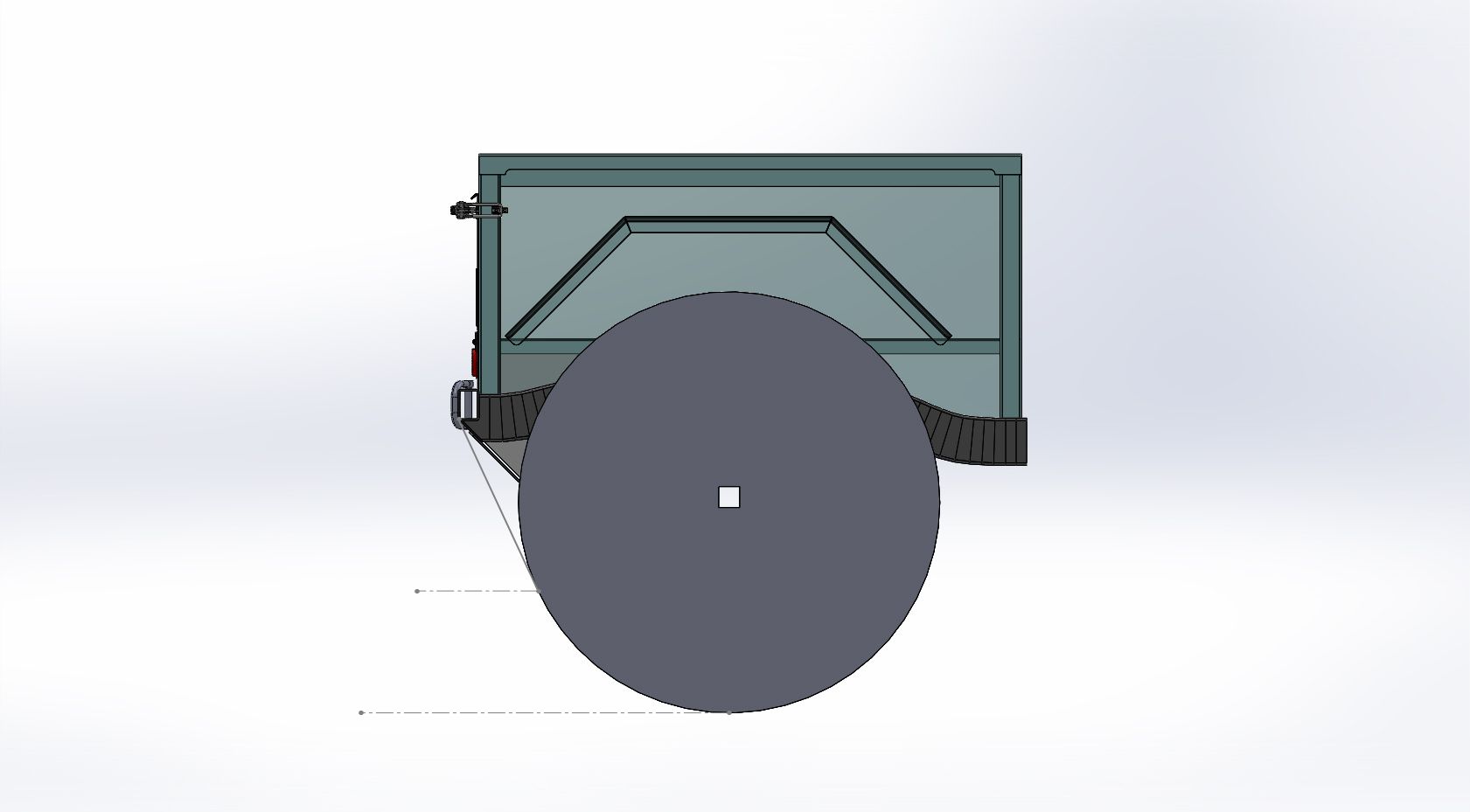
Here I am just trying to get a better idea of the scale of everything. Originally I thought I wanted the bed to be level with the lip of the rear of the tub. In the end, I think I decided to drop the bed slightly to help make the bed a little obtrusive. I am going to drop the bed about 1.25" below the lip on the back of the tub.
I believe this will leave me with a bed that is about 17-18" deep to the top of the rail. The bed should be about 42" wide and 51.5" long. That seems like a decent amount of space for a guy coming from a flat fender. I should have no problem laying the spare tire down in the bed with room to spare. With a 40" tire I should have almost a foot of extra space.


This was my experiment on how to build the bed rail system. The top of the tube as been cut to a 30 degree angle with the a section of what would be the inner wall removed. That should allow a flush surface for inner bed wall to attach to. That would give me a nice perimeter flange to secure the bed wall panel onto.
The tube is 2x2x1/8" wall. I will have those at the 4 corners of the bed. I need to come up with a way to have them easily and cleanly attach to the frame. I don't want the bed to be a completely welded to the frame assembly. I want to be able to remove the bed frame for paint. I believe it will be body color while the frame/bumper will just be black.
One crazy idea I have is to use one of the vertical bed posts as the fuel filler for the fuel tank. I could french in one of those pop-up motorcycle fuel fillers in the bed rail. Run the fuel down the post. Then french in some kind of 90 bend to the bottom which would turn towards the tank. That would completely hide the filler system?
The top cap is a piece of 5" wide sheet/plate/bar that I formed in my press brake. I think I might shorten up the outer vertical flange a little bit. It looks a bit tall to me. Taking off like 1/4-1/2" might make it look a bit better?

This is going to be the final rearward position of the bumper. The frame is going to be bobbed about 18" or so. I will need to drop the bumper about 2.5" I believe. I will be trying to do this similar to the front bumper where I can get the bumper into place before completely cutting the bumper off. I don't know if this really helps anything, but it can't hurt. The departure angle should be pretty good. The chassis is at full bump right now. I suspect the suspension will be about 5-6" up at ride height.
This should give me a bed about 51.5" long depending on how much space I have from the back of the tub to the front of the bed. I think about 1/2" should be enough gap/space?

Here I am just trying to get a better idea of the scale of everything. Originally I thought I wanted the bed to be level with the lip of the rear of the tub. In the end, I think I decided to drop the bed slightly to help make the bed a little obtrusive. I am going to drop the bed about 1.25" below the lip on the back of the tub.
I believe this will leave me with a bed that is about 17-18" deep to the top of the rail. The bed should be about 42" wide and 51.5" long. That seems like a decent amount of space for a guy coming from a flat fender. I should have no problem laying the spare tire down in the bed with room to spare. With a 40" tire I should have almost a foot of extra space.


This was my experiment on how to build the bed rail system. The top of the tube as been cut to a 30 degree angle with the a section of what would be the inner wall removed. That should allow a flush surface for inner bed wall to attach to. That would give me a nice perimeter flange to secure the bed wall panel onto.
The tube is 2x2x1/8" wall. I will have those at the 4 corners of the bed. I need to come up with a way to have them easily and cleanly attach to the frame. I don't want the bed to be a completely welded to the frame assembly. I want to be able to remove the bed frame for paint. I believe it will be body color while the frame/bumper will just be black.
One crazy idea I have is to use one of the vertical bed posts as the fuel filler for the fuel tank. I could french in one of those pop-up motorcycle fuel fillers in the bed rail. Run the fuel down the post. Then french in some kind of 90 bend to the bottom which would turn towards the tank. That would completely hide the filler system?
The top cap is a piece of 5" wide sheet/plate/bar that I formed in my press brake. I think I might shorten up the outer vertical flange a little bit. It looks a bit tall to me. Taking off like 1/4-1/2" might make it look a bit better?
1 - the lower the bed rail, the easier it is to see over it when you're backing up
2 - is that your bed cap or will the metal form the sides and bottom of the box as well?
3 - I think fuel fillers in bed caps are cool, but keeping them scratch-free is a challenge as is tying it into fuel tank (but what I've done the tank fill was inside the frame rail so there was zero access to it when the bed was installed.... point is, mock it completely up first.
enough of me - back to lurking.
You mentioned the rear bumper being lower than where the frame rail currently is. Just wondering why?
For departure angle, I would want higher.
I was going to point out a comment made by @cjmoon as I am contiplating the bed options on my ute project. Anyway his point was that the hump down on the frame after the rear spring mounts is not needed, and you could fab up the frame going straight back from that point.
And another totally unrelated question. 10 years on Mud with 369 posts? Some pretty heavy hitting posts too!
- Thread starter
- #253
1 - the lower the bed rail, the easier it is to see over it when you're backing up
2 - is that your bed cap or will the metal form the sides and bottom of the box as well?
3 - I think fuel fillers in bed caps are cool, but keeping them scratch-free is a challenge as is tying it into fuel tank (but what I've done the tank fill was inside the frame rail so there was zero access to it when the bed was installed.... point is, mock it completely up first.
enough of me - back to lurking.
I like input!
1-I'd agree. That is what I was thinking. I also have the tailgate lower than the bed rail to help see tight behind the truck too. There is a fine line when it starts to look a little funny though.
2-The 1/8" steel will just form the bed rail/cap. It will give me something to tie down to. It should be durable. It should be thick enough to tap for the fasteners that hold the aluminum bed panels onto the framework.
3- Yup, still not decided yet for sure. I don't really want the filler in the bed taking up space. I don't really want the filler hanging outside where it could clutter up the looks and perhaps damaged on the trail.
- Thread starter
- #254
You mentioned the rear bumper being lower than where the frame rail currently is. Just wondering why?
For departure angle, I would want higher.
I was going to point out a comment made by @cjmoon as I am contiplating the bed options on my ute project. Anyway his point was that the hump down on the frame after the rear spring mounts is not needed, and you could fab up the frame going straight back from that point.
And another totally unrelated question. 10 years on Mud with 369 posts? Some pretty heavy hitting posts too!
The bumper won't be below the frame, but also not resting on top of it. The bumper will be frenched down into the frame similar to how I did the front bumper. The chassis is at full bump right now. The bottom of the bumper is 24.25" sitting on top of the rail. I will probably sink it about 2.5" into the frame. Add about 6" uptravel at ride height and that gives me roughly 27.25" under the rear bumper. That seems plenty high with it so close to the rear tire. The departure angle should be in excess of 60-65 degrees.
I don't want to remake a new section of rear frame.
I joined Mud a long time ago when another cruiser project almost took off.....never happened. My old account still worked when I started this one. I'm not really a 'Toyota' guy per say, but I didn't want to be labeled as a 'Jeep' guy either so I decided to branch out. Mostly they all have an engine in the front, transmission and transfer case in the middle, a pair of axles, and 4 tires.
- Thread starter
- #256
can you fit a small fuel tank in front of the rear axle under the bed
Perhaps, but I am going to be mounting the battery, air compressor, and muffler in that space.
I would also shy away from multiple tanks with the fuel injection.
- Thread starter
- #257
Just a wee bit...

Working on the rear bumper prep and getting ready for the frame cut. The bumper will be the same design as the front with the tapered/pocketed ends along with the JATE rings for recovery. I believe I will also add a mounting plate for a pintle hitch. If I don't do it now it will be really hard later.
I added a few updates to the computer model also....

The departure angle looks like it is going to be about 65 degrees with the fuel tank tucked above the tire centerline at ride height. The fuel tank looks like it will be about 26 gallons give or take.
Things will probably be pretty slow as parts trickle in for the next week or two.

Working on the rear bumper prep and getting ready for the frame cut. The bumper will be the same design as the front with the tapered/pocketed ends along with the JATE rings for recovery. I believe I will also add a mounting plate for a pintle hitch. If I don't do it now it will be really hard later.
I added a few updates to the computer model also....


The departure angle looks like it is going to be about 65 degrees with the fuel tank tucked above the tire centerline at ride height. The fuel tank looks like it will be about 26 gallons give or take.
Things will probably be pretty slow as parts trickle in for the next week or two.
- Thread starter
- #258
I like those days I get to make big visual changes.....

Today I got the rear bumper tacked into place and was able to remove the 'extra' 18" of frame I didn't need any longer. This made a MASSIVE visual difference to the feel of the vehicle as a whole. It also made the shop feel a few feet larger too!
There is 14" between the bumper and the next crossmember for the fuel tank. I believe I can get about a 25 gallon tank in that location before things start to get in the way. The departure angle should be about 65 degrees. My hope is that will let me make the most of the 112" wheelbase. I have a few things in Moab that are on my bucket list which I have been denied continuously in the 85" wheelbase on the flatty.
Now I need to make all the brace plates for the bumper to the frame along with the mounting flange for the rear of the fuel tank skidplate.
Some misc pictures...

I think the frame bob was a net loss on weight. I forgot to weigh the new rear bumper but I can get it off the computer tomorrow and it should be pretty close.
- Thread starter
- #259
Just a bit, trying to get back in the groove...


This is the rear bumper transition flange. The gas tank skidplate will bolt to the bottom of this flange. It will use the same 10mm clip nuts that the belly skidplate is going to use to keep parts/tools common.
Some other misc things....

Upper Radiator hose. This is the upper hose from a 2007ish GM Trailblazer with a 5.3/6.0 LS engine. I only had to remove about 1" of the radiator end of the hose. This is the GATES 23194 version.

Lower Radiator hose. This is an upper hose from a 1985ish Jeep CJ7 with the 4.2 I6 engine, Dayco B71013. I did have to trim both ends of the hose a fair bit, carefully, but it ended up fitting very well.

Next project.....
These blocks are going to become the mounts for the bed corner posts.
- Thread starter
- #260
Time to learn a new skill....

I finally pushed the AC switch on my TIG welder for the 1st time. The last time I did some aluminum AC TIG welding was probably 20 years ago for about 15 minutes....
This project is about learning new things and developing my skills as a fabricator. There are a lot of things that I am going to make out of aluminum for this truck......front fenders, roof, rear window panels, 2pc doors, bed panels, gas tank, rear fenders, etc.
Much to learn.
While the welding sample was cooling between passes I decided to cut a little sample of this new shinny metal and test a few things in my new press brake.

This will help me when folding parts. This is 1/8" 5052-H32 material. It seems to bend very clean with no signs of cracking even with a fairly tight corner radius.

Looks at all that shinny metal....many sheets to come....