
Found some pics of the final assembly.


Navigation
Install the app
How to install the app on iOS
Follow along with the video below to see how to install our site as a web app on your home screen.
Note: This feature may not be available in some browsers.
More options
Style variation
You are using an out of date browser. It may not display this or other websites correctly.
You should upgrade or use an alternative browser.
You should upgrade or use an alternative browser.
Build Blender, My LX450/FZJ80 + FJ45esk + GM + Land Rover crazy concoction
- Thread starter Mieser
- Start date
Member Builds and Stories
This site may earn a commission from merchant affiliate
links, including eBay, Amazon, Skimlinks, and others.
If it's possible, it's also a good idea to make sure the ports on the ram are vertical. It makes bleeding the system considerably easier.
@2fpower can you tell a significant difference in assist from one direction to the other due to the size of the ram shaft? The piston area turning right should be MUCH bigger than the piston area turning left.
@2fpower can you tell a significant difference in assist from one direction to the other due to the size of the ram shaft? The piston area turning right should be MUCH bigger than the piston area turning left.
- Thread starter
- #223
Found some pics of the final assembly.View attachment 1397574 View attachment 1397575 View attachment 1397576
Great pics, thank you.
Yeah, no way the ram/mount would fit there on mine. At full bump my crank pulley is only about 1 inch away from the axle tube.
- Thread starter
- #224
If it's possible, it's also a good idea to make sure the ports on the ram are vertical. It makes bleeding the system considerably easier.
@2fpower can you tell a significant difference in assist from one direction to the other due to the size of the ram shaft? The piston area turning right should be MUCH bigger than the piston area turning left.
Just a note on the assist force. At 1000psi the difference is only about 300 lbs on my ram. 1700pounds the big way and 1400 the little way.
On my install, I also think the difference in ram force is opposite the steering if I am thinking about it right. There should be a difference in force in the steering box because one side of the piston has a reduction in area from the input shaft and ball mechasism.
If it's possible, it's also a good idea to make sure the ports on the ram are vertical. It makes bleeding the system considerably easier.
@2fpower can you tell a significant difference in assist from one direction to the other due to the size of the ram shaft? The piston area turning right should be MUCH bigger than the piston area turning left.
No, can't really tell a difference; however, never thought about it and tried to gauge the difference. At idle, it does not have tons of power. Fine for driving normally; however, on a trail and in some debris, I sometimes drop it in neutral and kick up rpm.
Sorry for hijack of your thread. Carry on.
- Thread starter
- #226
No, can't really tell a difference; however, never thought about it and tried to gauge the difference. At idle, it does not have tons of power. Fine for driving normally; however, on a trail and in some debris, I sometimes drop it in neutral and kick up rpm.
Sorry for hijack of your thread. Carry on.
No hijack, that is good info. It would be interesting to know what the pump is putting out for pressure.
In my application there are a few ways to make the gm pump put out more pressure. They make a few different pulley sizes for the pump. If you are seeing an increase in pressure with a little more rpm this could be an answer. The other option is to mod the pump valve assembly for a little extra pressure.
I am interested to see how many mods I have to do on mine to get it to where I want.
I may plumb in a hydraulic pressure gauge port so I can take some various readings.
- Thread starter
- #227
Moving along.....

I was able to get a rough mockup done on the hydro assist ram in preparation for the positioning of the winch/bumper mounting. Overall it ended up working out really well! The TRE's where a bit different to work with. I ended up making a mini-mount for the fixed end of the ram out of some thick bar stock. It was drilled and reamed to create the tapered hole for the TRE. I decided to mount the fixed end TRE vertically. This should make disassembly a little easier in the future since I will be able to drift out the tapered end from the top. The general spacing and layout worked out better too. The mount is a short stocky little unit that should have very little leverage on the frame rail. I will even be able to brace it to the grill crossmember to spread out the load a little bit. I am temped to add a 10 gauge frame pad up around the sides of the frame to spread the load out even more. I will sleep on that one....
The 8" stroke ram ended up being just about perfect for length. The ram bottoms out JUST before the steering box does internally. I also took a rough stab at adjusting the steering stops so they bottomed out the same time as the ram. I was able to adjust the steering stops in a little bit without any ill effects. The tires still cleared the radius arms and the CV joints didn't feel like they where binding or anything. I am really liking how tight this chassis can turn with a 40" tire and the proper wheel. The front frame is only 30" wide to the outside.....but the axles are 63" wide and I am almost 80" wide with the wheel/tire package.
Some misc pics....

The fixed end ram mount. I need to add a brace to the grill crossmember along the back. I am still temped to add a frame bad to spread out the load from that mount a little bit more around to different surfaces of the frame.

Preview of the winch mounting position with the paper mockup.

The skidplate that I am building under the 8274 winch drum as part of the mounting system will also be able to protect the hydro assist ram as planned. Yipee.

I did have to modify the aluminum hawse for the winch mount ever so slightly. I ended up needing to take 3/16" off one side to help it clear the bumper....
More soon.
- Thread starter
- #228
Making progress....

I finished up the frame mount for they assist ram. I plated the frame with 10 gauge around 3 sides. I also tied it into the grill crossmember. I don't think it is going to go anywhere now ever.


This car is getting something a little bit different for recovery points. I am going to use some JATE rings from a military Land Rover like a Wolf 90/110. One thing I have never liked is D-ring mounts that hang out in front of the bumper....and how they deal with side loads. The thing I really like about these is that the mounts where very simple and clean. The ring folds almost flat against the bumper also. I should be able to pull in a variety of directions. In the out position there is plenty of room to attach a winch hook, hard or soft shackle, or loop a strap. I will be using these on the rear bumper also to make things look uniform.
My funny name for them...
Lip Rings
Some details and tips....

BEST WELDING HELMET MODIFICATION EVER!
Thanks go to DanielBuck for this idea. Now I need to glue it on or something. Maybe some industrial velcro?

Shop tip.
Sometimes when you are using a square on the edge of tubing the radius is taller than the edge. This can make marking the middle of the tube a challenge since it just isn't half of the tube. If you mark from both sides and slowly adjust things you can find the dead center.

Welding around tubing this this kinda sucks, but the helmet light helps a ton!
- Thread starter
- #229
Front bumper part two...


Most of the front bumper and winch mount is done. Now I can start trimming the frame to set the final position of the bumper. It is going to be dropped down about 2" into the rail. The remaining height of the frame will be taper cut. I will be making a bunch of reinforcement plates to spread the load out to the rails and slightly change the profile to the eye.
Dropping the winch will allow the drum skidplate to also protect the assist ram. Lowering the winch will also get it totally below the main grill opening which should help preserve cooling capacity with this large winch on the front.
A few details...

Paper templates glued to chip board to make metal parts...

Bend the metal and trim trim trim to fit in the end of the bumper....twice.

Weld into the end of the bumper.

Add a hole into the end of the bumper. Now I can attach a 1/2" shackle if needed to rig something to the side of the vehicle. The pocket also works for a jacking point. I have a few other uses in mind for later....

Winch mount with skidplate under the drum. And the skidplate will protect the hydro assist ram.

This is about the final forward position of the bumper. The 8274 is a bit deep, but I think it is worth it for that much winch.

A better shot of the skidplate.
Hopefully tomorrow I can start trimming the frame for the final winch position! It looks like I get to bob about 3.25" off the end of the frame!
Are your Lip rings load rated?
They look like a good idea, easy to put a strap through.
They'll certainly give you a different look
They look like a good idea, easy to put a strap through.
They'll certainly give you a different look
- Thread starter
- #232
Are your Lip rings load rated?
They look like a good idea, easy to put a strap through.
They'll certainly give you a different look
Yes. They are a MoD military part for 'Wolf' series Land Rovers. Pretty common in Europe.
- Thread starter
- #233
Keep up the good work and new ideas, love the bumper tow hooks.
Is that a bridgeport?
Thanks. The mill is a Bridgeport Knee mill Clone I have available at work. Its handy for the odd thing I can't do at home, but every time I use it I want one at home....
Thanks. The mill is a Bridgeport Knee mill Clone I have available at work. Its handy for the odd thing I can't do at home, but every time I use it I want one at home....
That would be a very handy tool to have around! There is something very therapeutic about milling.
- Thread starter
- #235
Only a bit more today.....I ran out of welding gas and decided to call it a day.


This is basically what the front bumper is going to look like. I still need to add on all the reinforcement plates to the frame. Overall I am pretty happy with it. The winch is just low enough the top sits below the main grille opening which should help air flow. The hawse sits a little low, but I adjusted the tapered cut in the frame to 55 deg to help cover that up a bit. It is still a bit exposed but everything is a trade off. The aluminum hawse is cheap enough I could replace it and not feel too bad about it.
Some details and tips....

The approach angle isn't too bad. I wish it was better, but the 8274 is a pretty dang deep winch front to back.

This is the skidplate on the bottom of the winch mount that will protect the winch drum along with the assist ram for the steering.

This worked out pretty well. I was able to cut through about 80 percent of the frame before I set the bumper in place. Once the bumper was tacked I was able to insert the saw blade into the slot and finish cutting off the frame. This let enough of the front frame brace stay intact until the bumper could support things.
- Thread starter
- #236
Two less brackets to make now....

Pretty simple, but kinda took forever.
Tip.

Sometimes taking a little extra time to lay out the brackets lets you eliminate some cutting. I still want a plasma table and a few robot helpers....

Pretty simple, but kinda took forever.
Tip.

Sometimes taking a little extra time to lay out the brackets lets you eliminate some cutting. I still want a plasma table and a few robot helpers....
You're not a robot?!
- Thread starter
- #238
I am building this thing two brackets at a time....
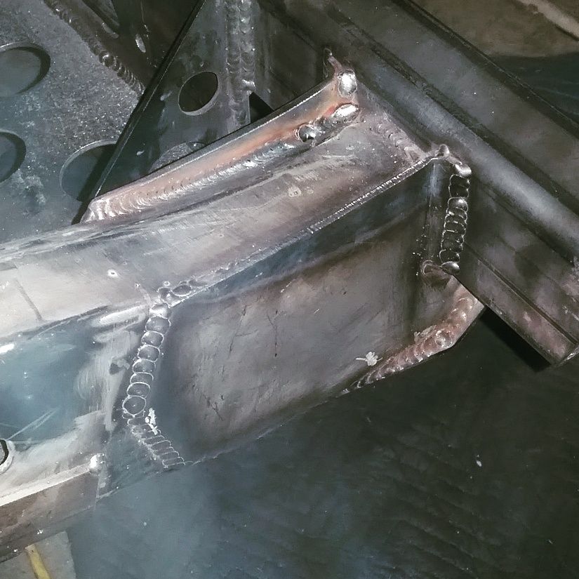
These are the side plates that tie the bumper and winch mount into the frame. They are 10 gauge cold roll plate like the rest of the brackets. I really like this thickness of material. It seems like a good compromise for overall strength, weldability, a good match to the stock frame thickness, etc. For the section that overlapped the weld from the bumper to the OE frame I added a small 1/2" flange to move the weld outboard to a fresh area.
Now to make another pair for the drivers side.
Fab tip.

If you ever end up with an odd inside cut like this. Score the metal with a small cut off wheel about 50% through. You don't have to get into the corners perfectly at this point.

Usually you can break out the piece with a section of pliers. Then clean up the edges with a triangle and/or round file.
Note the extra tang length for the folds. That makes it easier to bend generally. I bent these tangs over the edge of a table with everything clamped down. I just used a big crescent wrench to get enough leverage to fold the tang. Once it was fit to the frame I trimmed it to length.
Preview for the next few days...

- Thread starter
- #239
3.5 brackets today!


I was able to finish off the sides plates on the drivers side to match the work done yesterday. The top cap for the passenger side was also finished. I made both but ran out of time to finish up everything.
It's hard to see, but the top bracket has a gentle 'swoop' to it that matches the OEM frame bend. I like little touches like that....
I think tomorrow I will be DONE with the front bumper fab! Yipee!
How did you weld this? TIG, MIG like TIG or overlapping spot welds?