B engine compression & leakage testing along with glowplug & injector replacement

This site may earn a commission from merchant affiliate
links, including eBay, Amazon, Skimlinks, and others.

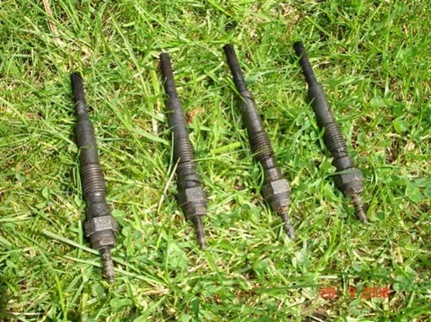
Here's all the ND plugs removed. One reason I wanted to replace them (apart from the "routine maintenance" reason) was because they were accidentally left energised for at least 20 minutes (probably way longer) while I had the steering column dismantled (which caused the ignition switch to stay in the glow position). I noticed my mistake only by smelling the burning smell coming from the baking of the dash paint around the glow controller! But they don't seem to have suffered any harm from their experience:
Glow04.webp

And here are the new plugs getting torqued down.

Glow08.webp

I couldn't find any torque specs in the FSM so 10 N-m (90 inch-lb) seemed reasonable - Accomplished with just one finger on this little torque wrench:
Glow04.webp
Glow08.webp
 
Well I did "compression testing" on all cylinders today too. And I looked at doing "leakage testing" - but predictably - I ran into problems there.

But at the moment I no longer feel in the right mood for posting all that stuff. --- Need a break from this damned keyboard. (And another drink of ALCOHOL.)

Later on I'll post up figures relating to voltages and glow times for the new HKT plugs too.

One thing of interest to me - is that after doing all the compression testing and farting around - I managed to restart the engine without glowing it. (I tried because I couldn't be bothered refitting the busbar.) Sure - It took a few more revolutions than normal to fire up but when it did - it ran smoothly straight away! Previously I had thought it wouldn't start without glowing if more than half an hour or so had elapsed since last run.
 
Right - I must post my compression test results. But before I do, this bit (in the red box) in the FSM got me interested.

FSMpage.webp

(I know - I should read the FSM more often :D)

Why are they so fussy about avoiding getting oil on glow plugs? - I thought it would just burn off the lower part when they're first used? Or perhaps they think the oil will accidentally set off a combustion explosion when you're not expecting it?

And why care about a bit of oil on the terminals? I thought that would be a benefit rather than cause harm?

I was going to put a dab of copper grease (anti-seize) on the new plugs threads before inserting them. But in light of this FSM warning (and because the old plugs were easy to remove too) - I was too scared to!!!
FSMpage.webp
 
You're such a tease Tom. :D

Ha Ha. I'm getting there Drew. Actually the first reading I took - 400psi had me rapped --- thinking she was absolutely pristine!

Anyway - Compression testing

Here's a page from the FSM showing that 427psi is the target for each cylinder and that the cranking speed should be 250rpm. And that the variation between cylinders should be no more than 10%.
(The manual shouldn't say 28psi - I believe they've said that only because 28psi is 10% of the lower limit of 284psi)

FSMcomp.webp

Right so all glowplugs are removed. And I've unplugged the EDIC here (to avoid the cylinder that I'm testing from "firing" and blowing my gauge to bits):

Compression01.webp

Note that the manual shows only one connector being opened. since I found 2 connectors I disconnected them both.


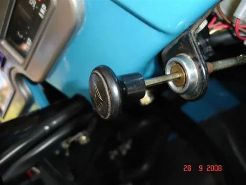
And here is the hand throttle being used to hold the intake manifold butterfly valve open:

Compression02.webp
FSMcomp.webp
Compression01.webp
Compression02.webp
 
:hhmm: Now - I don't have a tacho so I gotta measure cranking rpm some other way. ---- Lucky I've got a lot of old gear.
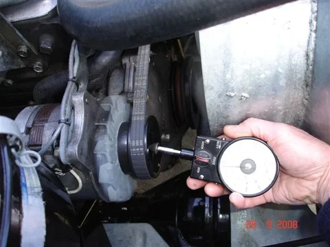
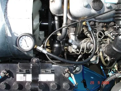
Here's me measuring the cranking rpm of the alternator pulley:

Compression03.webp

Now the crank pulley rpm will be inversely proportional to the ratio of the PCDs (pitch circle diameters) of the alternator pulley and crank pulley.

And the PCD ratio is near-enough the same as the outside diameter ratio -- which I can easily measure with a super-large set of outside-callipers that I have.

Alternator pulley: 82mm Crank pulley: 145mm
Measured alternator rpm = 420

So my cranking rpm = 420 x 82 = 237.5 rpm
................................. 145

:hhmm:... I thought I might exceed 250 because my starter and battery are in good nick and without the glowplugs she sure whizzes over!
Compression03.webp
 
Right the engine is hot - after a good run, all glowplugs are removed, EDIC is immobilised, hand throttle is open, son sitting in driver's seat - key in hand (wishing he was back inside the house listening to "death metal" on his ipod or persecuting the neighbours with his drumming practice routine)................

Now the info sheet supplied with my compression gauge says that you record each reading after 8 revolutions (or something like that) ------- What a load of dribble IMO.

I recorded each readings after the gauge appeared to settle and looked like it wouldn't go higher (which was probably around 8 compression strokes on that cylinder):

Compression04.webp

My results were.....................


:D


;p


:cool:


No1: 400psi - No2: 340psi - No3: 360psi - No4: 420psi

So the average of those is --- 380psi
So I reckon my max variation (10%) should be 38psi

This means all my readings should lie between 342psi and 418psi to achieve "good engine" status.

Well - Near-as-dammit they do (What's a measerly 2 psi amongst friends?)
Compression04.webp
 
Now then - the tricky part................

Cylinder leakage testing

Have to admit that when I bought the tester, I hadn't thought through how to use it on my B diesel.

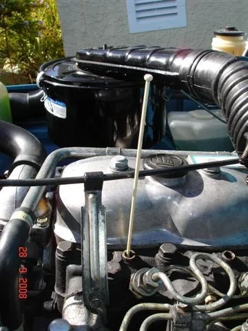
I subconsciously thought I could do what I've always done to get a piston at TDC (top dead centre)...... Put the plastic knitting needle in the sparkplug/glowplug hole trick to "feel" when the piston is at the top of a compression stroke. Like this:

Leakage03.webp

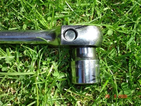
While I turn the crankshaft (glowplugs removed and gearbox in neutral) using a ratchet and 24mm socket on the crank pulley nut:

Leakage05.webp

But this FSM picture shows the precombustion chambers block the knitting needle's access.

Bengine2.webp

(:hhmm:Wonder if Mum will notice her knitting needle is a bit scratched and greasy now?)
Leakage03.webp
Leakage05.webp
Bengine2.webp
 
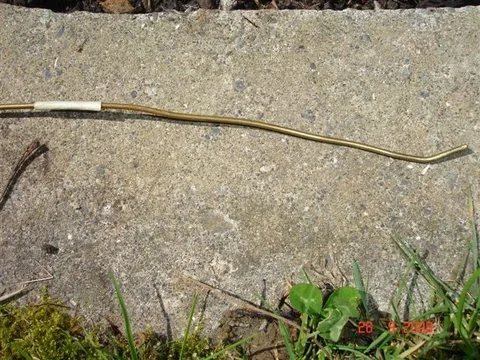
So the next brilliant idea was to introduce a "technical bend" to a bit of bronze welding wire so it is able to pass through the holes in the precups --- and thus allow me to "feel" the top of a piston:

Leakage04.webp


But yep.......... Dismal failure also.:mad:

Oh --- I should say something about a leakage tester for those not familiar with them I suppose.....

You use it to feed compressed air into a cylinder when its piston is at TDC and both inlet and exhaust valves are closed.

You can then locate the source of compression loss by listening at these places:
* Oil dipstick for leaking compression rings
* Radiator fill cap for head gasket/cracks
* Adjacent port for head gasket
*tail pipe for exhaust valve
* air intake for inlet valve

And I wonder now - Is TDC so important so long as you have both inlet and exhaust valves closed?

I could put a protractor (I think that's what it is called) on the crankshaft pulley and go off the degree marking on that? But hardly worth the effort?

But I ended up being stymied from going any further anyway cos at this point I discovered that the air supply fitting (brass one) on my tester was incompatible with the fitting I use in my garage (despite looking very similar):

Leakage01.webp

So that is where my leakage testing has reached at this point of time. --- I'm not sure whether I'll even bother to proceed with it - Because of the difficulty in determining TDC (but as I say TDC probably doesn't matter and I should be able to stop the engine spinning - as a result of the applied air pressure - by locking the engine in gear) and because I'm happy with the engine's condition anyway (nothing really there worth finding out about).

We'll see!
Leakage04.webp
Leakage01.webp
 
Having done leakage testing for years on aircraft engines, I think the main reason for TDC is it puts the crank throw and connecting rod in a straight line so it is easy to stop the engine from rotating. It is a bit of an adrenalin rush to be holding on the the propeller of a 1340 cubic inch (22 litre) engine with 100 psi going into a cylinder that is not on TDC. As your feet leave the ground you realise that letting go is only going to allow the engine to spin and whap you with the other propeller blade as you drop back to the ground...

I just looked at the glow plug bus bar on my BJ42 and you're right, it is different than yours - it is a flat bar instead.
 
Last edited:
Having done leakage testing for years on aircraft engines, I think the main reason for TDC is it puts the crank throw and connecting rod in a straight line so it is easy to stop the engine from rotating. It is a bit of an adrenalin rush to be holding on the the propeller of a 1340 cubic inch (22 litre) engine with 100 psi going into a cylinder that is not on TDC. As your feet leave the ground you realise that letting go is only going to allow the engine to spin and whap you with the other propeller blade as you drop back to the ground...

I just looked at the glow plug bus bar on my BJ42 and you're right, it is different than yours - it is a flat bar instead.

Thanks Wayne
I imagine an aircraft prop can do a lot more damage than a plastic radiator fan blade!
 
I'm fairly certain that 100 psi wouldn't be enough to move the truck if you just put it in 4th and set the parking brake. I, for one, want to see this leakage test happen :)

In fact, we can calculate it - bore is 95mm so area is ~11sq in. At 100 psi thats 1100 pounds of conrod pressure. torque is maximum 90deg from TDC (worst case) and the moment arm is equal to half the stroke, 105mm/2, so the total torque would be 378ft lbs.

The question is, can 378 ft lbs move the truck? 1:1 through the drive train and 4:.11:1 at the diffs means you have 1550 ftlbs at the wheels. I'll assume you're sitting on 30" tires, which have a moment arm of 1.25 ft, so the truck will move forward with a force of 1240lbs....

1240lbs is 31% of the trucks weight (I'm guessing about 4000lbs for a '40). Doing a little fancy math, if you were to park on a 18deg hill (or ~31% grade) you'd have about 1240lbs on your brakes. If you think your parking brake can hold you in that situation, you're fine. If not, can your service brakes hold you? If so, use those.

All of this assumes you're 90deg from TDC. Say, if you're only 10 deg off from TDC, there will only be a whopping 200 lbs on your brakes!! (equivalent to parking on a 3deg hill, (5% grade). Surely your parking brake and can handle that? I'd bet you can get within +/-10% of TDC by just watching the valves.

[Oh and great job on the other stuff. I'm surprised you had one "lowish" cylinder. Eh, I guess we all have to do it for ourselves before we believe the old maxim that compression tests only tell you things you were happier not knowing. When was your last valve adjustment?]
 
Tom,
Once again, great thread, lots of pictures and step by step. Perfect for a guy like me who has never done this before but wants to learn by trying. As to the leakage tester. I assume that Toyota service techs must have some guidance in the shop regarding how to carry out this test. I'm surprised that there isn't a step by step in the FSM or somewhere similar.
John
 
....I, for one, want to see this leakage test happen ...

I probably will go ahead and do it Drew. (I guess I've got to justify buying the thing anyway.)

I might stick an ammeter in the glowplug wiring too.


.....In fact, we can calculate it - bore is 95mm ............................ Surely your parking brake and can handle that? I'd bet you can get within +/-10% of TDC by just watching the valves....

:clap: I LOVE it!!!!!!!!

Actually I have strong views about "unnecessary thinking" and refuse to do crosswords or even answer questions from people who are doing them. My personality is such that I'd prefer to have the vehicle "jump forward (or backward) and surprise me" rather than go to all that trouble of calculating the risk. My "6th sense" tells me "4th gear with the handbrake on and I'll be fine".

Oh - And I didn't want to take the rocker cover off and disturb that gasket. So I'll have to think more about whether I want to change my mind there.

It's raining in my workshop and damned cold again too at present - so I have lots of time to think. (But that's USEFUL thinking rather than UNNECESSARY thinking Drew.)

.....[Oh and great job on the other stuff. I'm surprised you had one "lowish" cylinder. Eh, I guess we all have to do it for ourselves before we believe the old maxim that compression tests only tell you things you were happier not knowing. When was your last valve adjustment?]

Well it starts easily, idles smoothly, runs well, doesn't smoke (apart from the normal puff on start-up), uses very little oil etc --- so I'd have to be crazy to want to rip into it on the basis of these compression findings.

The last valve adjustment was .....................crickey.........................I'm looking back a long way..................found it --- (about 10mins later).....31 October 1981 at 41100kms!

Damn you Drew! You give me no choice now but to get a new rocker cover gasket and "adjust the tappets".

But at least I now have good reason to lift the rocker cover - which makes the leakage testing much simpler :):)

I suspect I never bothered repeating the tappet/valve adjustment in subsequent years because it stuck in my memory that "almost ziltch" adjustment was necessary back then in 1981!

And us oldies tend to lose our sense of time! What I did back in Oct 81 still feels "recent".


:cheers:
 
Last edited:
Tom,
Once again, great thread, lots of pictures and step by step. Perfect for a guy like me who has never done this before but wants to learn by trying. As to the leakage tester. I assume that Toyota service techs must have some guidance in the shop regarding how to carry out this test. I'm surprised that there isn't a step by step in the FSM or somewhere similar.
John

I did some searching and - yes - there are ways of doing it John.

For instance, I recall reading about little "whistles" you screw into the glowplug hole to determine when a piston is on a compression stroke with the inlet and exhaust valves closed.

(Strangely enough - I couldn't seem to determine a compression stroke using the "wet-finger-over-the-plughole-to-detect-rising-pressure" trick.)

But the methods described were generally too complex for me to be bothered with.

But right now - I don't think getting a piston at exact TDC is important so long as I have both valves closed (and so long as the engine cannot rotate far enough - as a result of applying air pressure into that cylinder - to open a valve). And Drew's now forced me to remove my rocker cover (thanks Drew :D) so I'll now have no problem determining when both valves are closed.

So my next step is to prepare for this by ordering a new rocker cover gasket and getting a new fitting (looks something like 1/8BSPT to airline) for the HarborFreight leakage tester so I can plug my air hose into it.

And I may just use 80 psi air pressure anyway (you'll have to repeat all your calcs Drew) because 100psi is right at the end of the tester's gauge scale as I recall (and as such - it is probably not recommended)

:cheers:
 
I might stick an ammeter in the glowplug wiring to measure the overall glow current too because I've got one that can measure up to 12A. --- I never imagined the glow current would be as low as 10.3A maximum! (according to the FSM). I always thought it was WAY higher than that.

Its odd, the manual is inconsistent. If the voltage measured at the bus bar is ~8.5V and the plugs are supposed to be .2 ohms (per the FSM) then the total current should be 42A per plug (168A total). This is very simple math. Granted, the plug resistance will rise over temperature, however I don't think its going to rise that much. Hell, what do I know... give it a try. (Maybe use a cheap ammeter)

Oh - And I didn't want to take the rocker cover off and disturb that gasket. So I'll have to think more about whether I want to change my mind there.

It's raining in my workshop and damned cold again too at present - so I have lots of time to think. (But that's USEFUL thinking rather than UNNECESSARY thinking Drew.)

Come now, the valve cover gasket is the easiest one on the whole truck, its about 1/8" thick rubber! If you think that will stress out your busy, busy, brain, you could have your :princess: do it for you... :D

Well it starts easily, idles smoothly, runs well, doesn't smoke (apart from the normal puff on start-up), uses very little oil etc --- so I'd have to be crazy to want to rip into it on the basis of these compression findings.

Agree fully.

The last valve adjustment was .....................crickey.........................I'm looking back a long way..................found it --- (about 10mins later).....31 October 1981 at 41100kms!

Oh now thats just sloppy! I wouldn't be surprised if that had a huge effect on your readings.

Damn you Drew! You give me no choice now but to get a new rocker cover gasket and "adjust the tappets". (I'll repeat the compression test only if I find insufficient clearance.)

Haha, we're going to have your truck down to the frame before you know it!

EDIT: One more thing - don't be surprised if you have the legendary rocker-arm divots that prevent you from getting a good valve adjustment. Be prepared to grind them, which means pulling the rocker assembly. I ground mine with a tiny grinding wheel in the dremel tool and lots of patience to keep things cool. I pulled it again about 5000miles just to check if they were doing ok and saw no sign of damage or divots.
 
And I may just use 80 psi air pressure anyway (you'll have to repeat all your calcs Drew) because 100psi is right at the end of the tester's gauge scale as I recall (and as such - it is probably not recommended)

:cheers:

Now that you mention it, I'm reminded that the standard pressure we always used to check aircraft engines is 80 psi. And I never heard of anybody doing a compression check on an aircraft engine, it can't compare with a leakdown test for giving you information on the engine.
 
...
So my next step is to prepare for this by ordering a new rocker cover gasket and getting a new fitting (looks something like 1/8BSPT to airline) for the HarborFreight leakage tester so I can plug my air hose into it......

I pick the gasket up today and I've already picked up an airline fitting I can use (not really the one I wanted though).

....If the voltage measured at the bus bar is ~8.5V and the plugs are supposed to be .2 ohms (per the FSM) then the total current should be 42A per plug (168A total). This is very simple math. Granted, the plug resistance will rise over temperature, however I don't think its going to rise that much. Hell, what do I know... give it a try. (Maybe use a cheap ammeter)....

A workmate used to always refer to electricity as "elec-trickery" and this is why!

Calculations are often all theoretical nonsense IMO.

I'll be careful with my meter.

And from the size of the wiring used - I wouldn't expect more than 30A maximum overall glow current. (I'm still dubious of the 10.3A FSM figure believing it to be low.)

Edit - Nov 09 - Back then I didn't realise the 10.3A FSM figure was a "per plug" figure. I now realise it is - and that this allows for a maximum expected TOTAL glow current of 4 x 10.3 = 41.2 amperes


...Oh now thats just sloppy! I wouldn't be surprised if that had a huge effect on your readings.......

You're right of course and I am very ashamed!!!!! (Sort of turns my claim that I keep my vehicle "well maintained" into "bullsh#t".)

And I really have no choice but to repeat the compression testing once I've done the tappet/valve adjustments. (They're bound to need adjusting after 200,000kms and 27years - and the more I think about it the more I agree that the adjustment should improve my figures.)


....One more thing - don't be surprised if you have the legendary rocker-arm divots that prevent you from getting a good valve adjustment. ....

Geee. Thanks Drew!

Now that you mention it, I'm reminded that the standard pressure we always used to check aircraft engines is 80 psi. And I never heard of anybody doing a compression check on an aircraft engine, it can't compare with a leakdown test for giving you information on the engine.

Yeah - Now that I think about it - I've seen 80psi mentioned alot in other people's test results.
 
Last edited:
Okey Dokey! I'm all set to do the tappets and redo the compression testing ...... but that have to wait till the weekend (assuming the weather will be kind then).

Meanwhile I'm trying to finish gathering data relating to my glow system. Hopefully it will be useful to myself and others (who own diesels that use the same glowplugs) for "faultfinding" in the event of our glow systems developing faults. (At present my glow system operates perfectly!)

(I obviously had to get my glow system working again anyway in order to get my engine restarted so it could be "warm and well lubricated" for the tappet adjustments and next round of compression testing.)

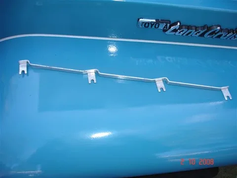
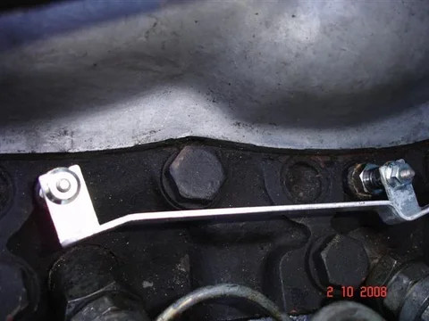
Here's a busbar connection:

2 Oct 003.webp

And here it is after the busbar has been cleaned up:

2 Oct 007.webp

And here is the whole busbar cleaned. (It is in perfect condition.):

2 Oct 005.webp
2 Oct 003.webp
2 Oct 007.webp
2 Oct 005.webp
 
This is how each of my HKT plugs are supplied:

2 Oct 001.webp

I decided to fit the "washered nuts" (inverted) from the old Nippondenso plugs to enlarge the electrical contact area for the connections - which I believe to be important because the terminals of the substitute plugs (that I am forced to buy now) have a smaller thread-size than the busbar was designed for:

2 Oct 002.webp

And here is how the busbar sits now:

2 Oct 008.webp
2 Oct 001.webp
2 Oct 002.webp
2 Oct 008.webp
 

Users who are viewing this thread

Back
Top Bottom