
I have some time to kill today, so I thought I'd start up a proper thread on this exhausting bumper build I've been working on.
I spent some time looking around at the different bumpers available online, but decided that's a lot of money, and why not use the opportunity to do something new, unique, and learn in the process. I had built tube bumpers for my previous vehicle, which worked out just fine, but I wanted something a bit more substantial for the Cruiser. Took inspiration from random images I found all over a Google Image Search, and ended up doing the following.
Now, I am not a welder or fabricator in any way, I'm just pretending to be one. A crappy welder at that. So don't expect any of the "close up shot of my one impressive weld" pictures.
All work has been done after the kids go to bed. This has been 2 weeks so far of VERY late nights in the garage.
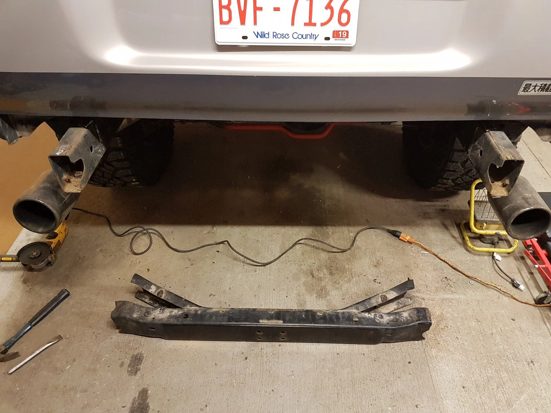
First up, I cut out the rear crossmember. I mocked something up out of cardboard trying to keep the crossmember, but decided I wanted to tuck everything in nice and close. So, no turning back now.
Then, I made a mock up out of cardboard.

Then, I took the cardboard apart, and translated that into paper form. I laid the pieces out on the bench with a big framing square and took a whole wack of measurements.

Took that to the computer and drew the pieces up in AutoCAD (but any other 2D drawing application that can output a DWG or DXF file would work fine).

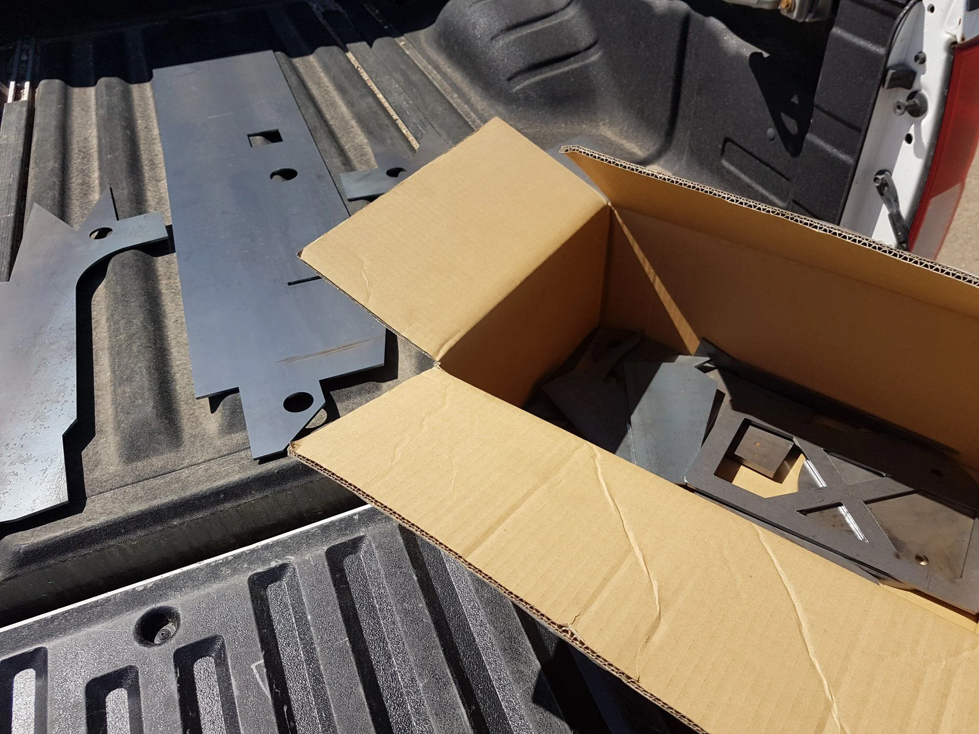
And then took that to one of our customers at work with a laser cutting table, and a couple hundred bucks cash later, I have a bunch of nicely cut metal pieces.
The main bracket/recovery hoops are 3/8", and the rest of it is all 3/16" mild steel. The recovery hooks are part of the mounting bracket itself, protruding out from the skin of the bumper so I expect they should be nice and solid.
At this point I'm feeling pretty proud of myself.
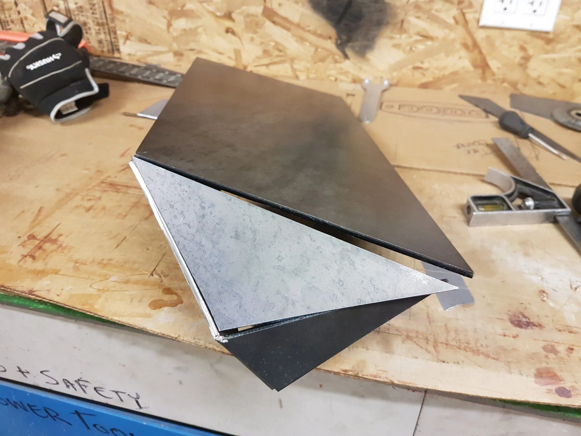
I had read one fellas build thread online somewhere where he took the metal, scored it with a grinder and folded it himself, not having a bender. I figured I'd do something similar.
DO NOT DO THAT. Turns out that cardboard doesn't make for perfect anything, and you WILL have to do some adjusting here and there of all your pieces. Make every piece separate and then tack them together. Otherwise you get the pieces that don't line up nicely, and can't just be pulled into position.
Cutting and bending also leaves a bigger opening than it would otherwise, that now needed to be filled with weld, and ground to something resembling a nice shape. It sucks.
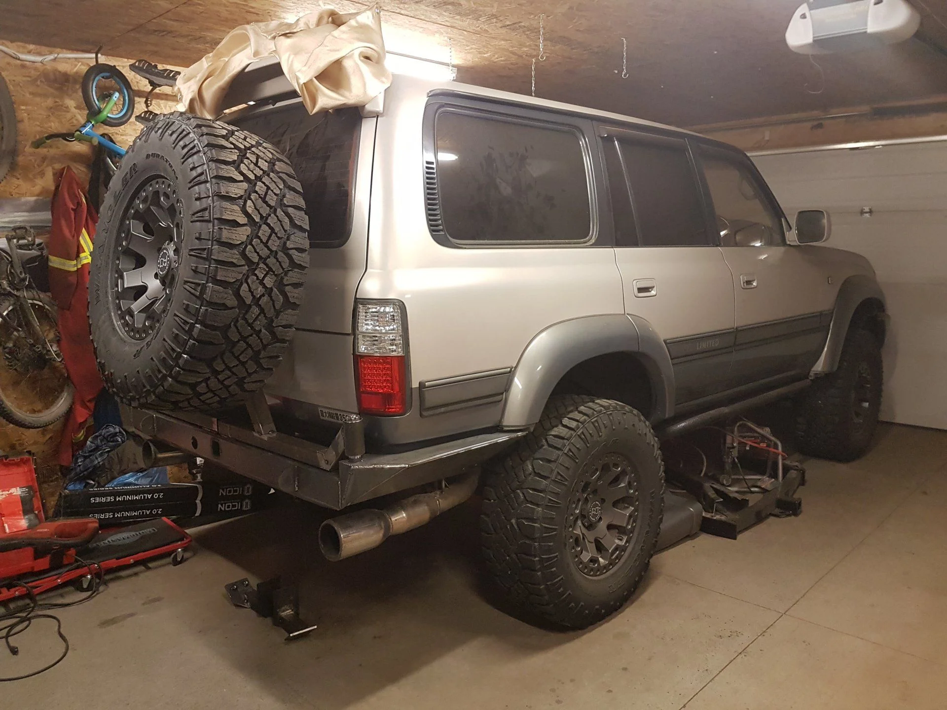
So, after a whole lot of extra time spend dicking around, I finally had something resembling a steel bumper. Then started working on the accessory side and the tire carrier. The spindles came from RuffStuff and seem nice and beefy. They are a solid machined 1.5" spindle and not the cast stuff, so hopefully they will last.

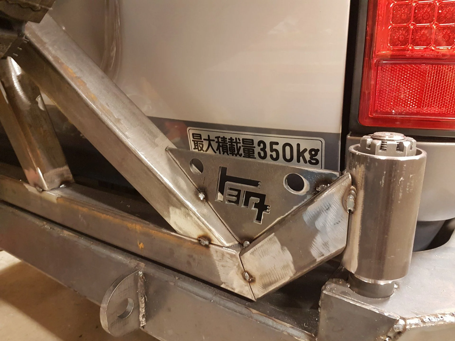
For the sake of being a geek and just because I could I had a couple of extra gussets made up with the TEQ logo incorporated into them.
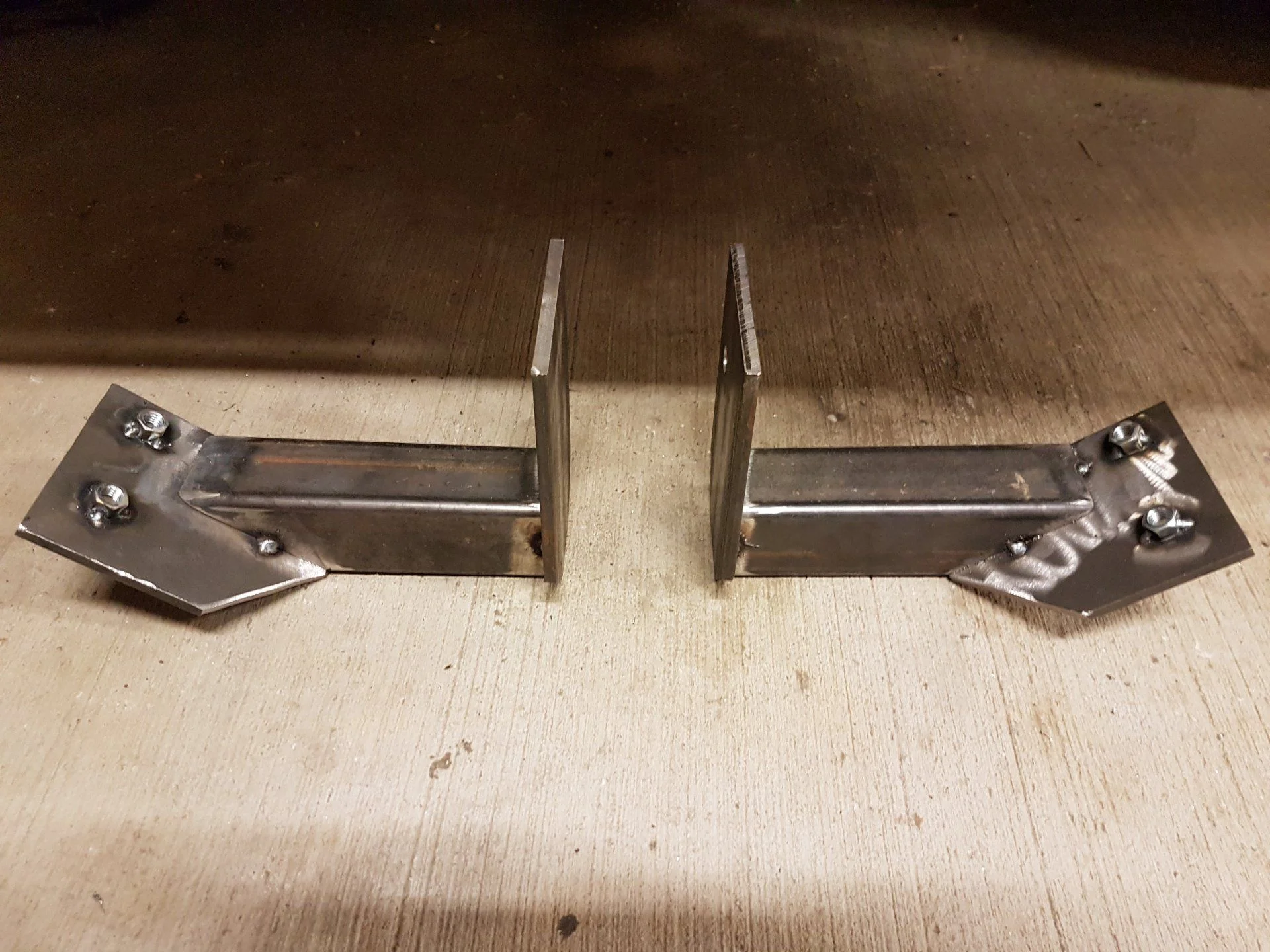
These tacked together brackets are what will be supporting the forward side of the wings. I'm not super happy with how the sides all turned out, but I guess I will be living with them. The wings are REALLY close to the body, so it looks cool, but I think a bit more room would have been nice to work with.
I know a lot of bumpers go the "full sheet from wing right to the frame" route for the supports, but I don't like the idea of all that muck being trapped on the side of the frame in there, which is why I left it open. This also lets me get this thing on and off without worrying about the current exhaust hangars, which I don't want to touch for a while yet.
These are also getting an extra gusset added to them to strengthen the plate that connects to the frame.
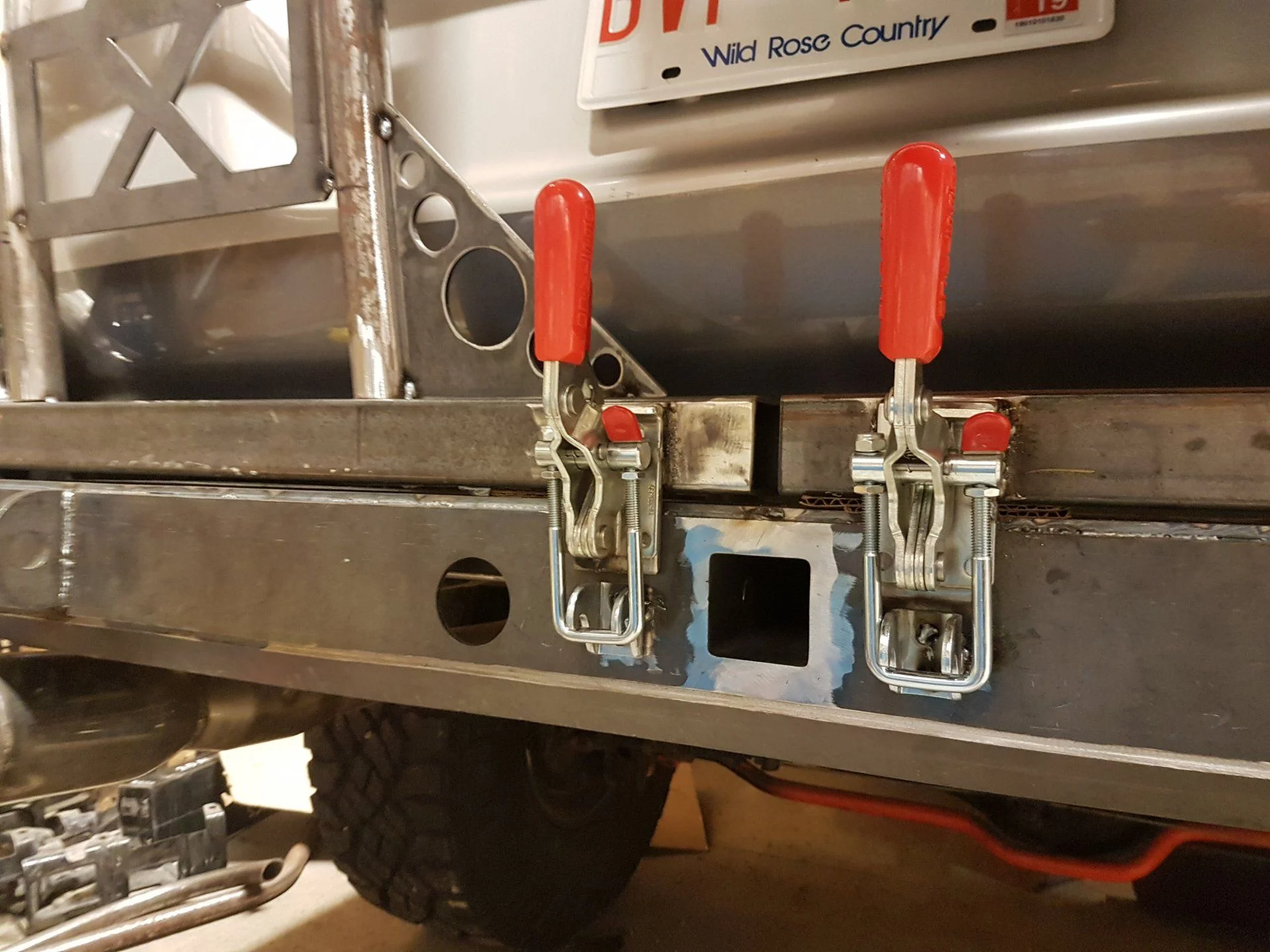
I went with the same Destaco type latches that everyone else does. I welded them into place because I didn't want to drill any more holes than I needed to. If one breaks, well, I guess I'm either screwed, or I'll have to weld a new one on. Not the end of the world.
There will also be some plastic material under the arms to help with a rattle free hold down. I got some from a customer at work, but it was 3/8" thick and that's a bit too much, so I gotta find something a bit thinner to work with.
Last night I was able to get pretty much all the crappy "fill in the gaps and grind the ever loving crap out of the corners" of the main bumper section done.
That was 3 1/2 hours of nightmare fuel.
That all leaves some extra gussets to weld onto that, add the spring pin to hold it open, the wing supports to weld and gusset, then do the finishing welds on the two carrier arms. When that's done, I can primer and spray.
I think I want to add an extra piece of support from the main frame brackets to the wing closer to the rear to help prevent any flexing from the spindle. The spindle itself doesn't flex, but I noticed that small amounts of movement from the wing side twisting translates into BIG movement from the tire carrier itself, especially when the tire is mounted. Some of that might be just that it was all tacked, but I think I want something a wee bit more solid if possible. Who knows, I'll see what and if I come up with anything. Either way it will be another VERY late night tonight.
I will add some more photos of the underside of the bumper (and all associated really ugly welds), how I mounted it to the truck, and things of that nature when I actually take pictures of them, most likely after it's all done.
I spent some time looking around at the different bumpers available online, but decided that's a lot of money, and why not use the opportunity to do something new, unique, and learn in the process. I had built tube bumpers for my previous vehicle, which worked out just fine, but I wanted something a bit more substantial for the Cruiser. Took inspiration from random images I found all over a Google Image Search, and ended up doing the following.
Now, I am not a welder or fabricator in any way, I'm just pretending to be one. A crappy welder at that. So don't expect any of the "close up shot of my one impressive weld" pictures.
All work has been done after the kids go to bed. This has been 2 weeks so far of VERY late nights in the garage.
First up, I cut out the rear crossmember. I mocked something up out of cardboard trying to keep the crossmember, but decided I wanted to tuck everything in nice and close. So, no turning back now.
Then, I made a mock up out of cardboard.
Then, I took the cardboard apart, and translated that into paper form. I laid the pieces out on the bench with a big framing square and took a whole wack of measurements.
Took that to the computer and drew the pieces up in AutoCAD (but any other 2D drawing application that can output a DWG or DXF file would work fine).
And then took that to one of our customers at work with a laser cutting table, and a couple hundred bucks cash later, I have a bunch of nicely cut metal pieces.
The main bracket/recovery hoops are 3/8", and the rest of it is all 3/16" mild steel. The recovery hooks are part of the mounting bracket itself, protruding out from the skin of the bumper so I expect they should be nice and solid.
At this point I'm feeling pretty proud of myself.
I had read one fellas build thread online somewhere where he took the metal, scored it with a grinder and folded it himself, not having a bender. I figured I'd do something similar.
DO NOT DO THAT. Turns out that cardboard doesn't make for perfect anything, and you WILL have to do some adjusting here and there of all your pieces. Make every piece separate and then tack them together. Otherwise you get the pieces that don't line up nicely, and can't just be pulled into position.
Cutting and bending also leaves a bigger opening than it would otherwise, that now needed to be filled with weld, and ground to something resembling a nice shape. It sucks.
So, after a whole lot of extra time spend dicking around, I finally had something resembling a steel bumper. Then started working on the accessory side and the tire carrier. The spindles came from RuffStuff and seem nice and beefy. They are a solid machined 1.5" spindle and not the cast stuff, so hopefully they will last.
For the sake of being a geek and just because I could I had a couple of extra gussets made up with the TEQ logo incorporated into them.
These tacked together brackets are what will be supporting the forward side of the wings. I'm not super happy with how the sides all turned out, but I guess I will be living with them. The wings are REALLY close to the body, so it looks cool, but I think a bit more room would have been nice to work with.
I know a lot of bumpers go the "full sheet from wing right to the frame" route for the supports, but I don't like the idea of all that muck being trapped on the side of the frame in there, which is why I left it open. This also lets me get this thing on and off without worrying about the current exhaust hangars, which I don't want to touch for a while yet.
These are also getting an extra gusset added to them to strengthen the plate that connects to the frame.
I went with the same Destaco type latches that everyone else does. I welded them into place because I didn't want to drill any more holes than I needed to. If one breaks, well, I guess I'm either screwed, or I'll have to weld a new one on. Not the end of the world.
There will also be some plastic material under the arms to help with a rattle free hold down. I got some from a customer at work, but it was 3/8" thick and that's a bit too much, so I gotta find something a bit thinner to work with.
Last night I was able to get pretty much all the crappy "fill in the gaps and grind the ever loving crap out of the corners" of the main bumper section done.
That was 3 1/2 hours of nightmare fuel.
That all leaves some extra gussets to weld onto that, add the spring pin to hold it open, the wing supports to weld and gusset, then do the finishing welds on the two carrier arms. When that's done, I can primer and spray.
I think I want to add an extra piece of support from the main frame brackets to the wing closer to the rear to help prevent any flexing from the spindle. The spindle itself doesn't flex, but I noticed that small amounts of movement from the wing side twisting translates into BIG movement from the tire carrier itself, especially when the tire is mounted. Some of that might be just that it was all tacked, but I think I want something a wee bit more solid if possible. Who knows, I'll see what and if I come up with anything. Either way it will be another VERY late night tonight.
I will add some more photos of the underside of the bumper (and all associated really ugly welds), how I mounted it to the truck, and things of that nature when I actually take pictures of them, most likely after it's all done.
")


") I'd say the most it moves at the top of the tire is maybe 3/4" to 1". I check the welds once a week for cracks in the powder coat and nothing yet, but we'll see what happens long term. I figure, Mike knows what he was doing when he designed it.
I'd say the most it moves at the top of the tire is maybe 3/4" to 1". I check the welds once a week for cracks in the powder coat and nothing yet, but we'll see what happens long term. I figure, Mike knows what he was doing when he designed it.