I recently finished integrating my ARB air locker into the factory switch and dash indicators, here is my write up....
The purpose of this project was to install ARB air lockers and have them integrated into the factory switch and dash indication. There are some other threads on this subject and I used that information to help get my start. Here is how I did it and maybe this information will help the next guy.
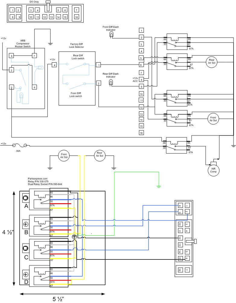
I started by researching the wire diagram for the factory locker system.

From that I created a diagram for replacement for the factory Diff Lock ECU.

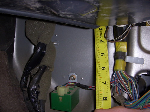
I measured up the factory location of the ECU and determined that I could fit standard relays in exact same spot.

I created a cardboard template to build a metal plate to mount in the location.
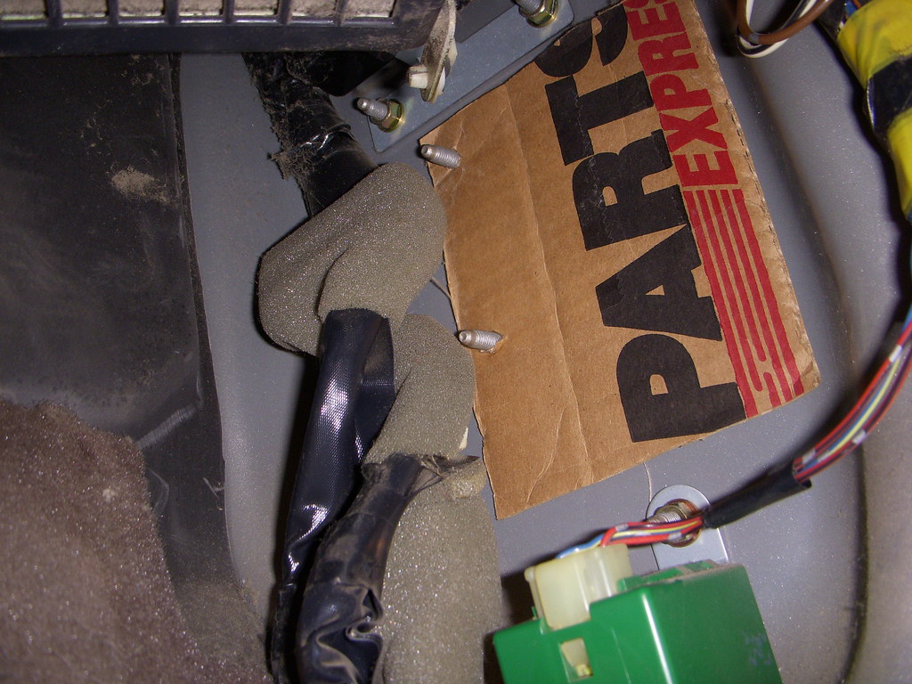
I purchased dual relay sockets from Parts Express, these worked nicely to pair up the relay for the locker with the relay for the dash indicator light. The bolt studs for the factory ECU also line up very nicely with the relays fastening clip but the holes in the relay need to be widened to fit over the stud. I chose a relay with a metal clip so it would mount a little sturdier.
www.partsexpress.com
Relay P/N 330-079
Dual relay socket P/N 090-844
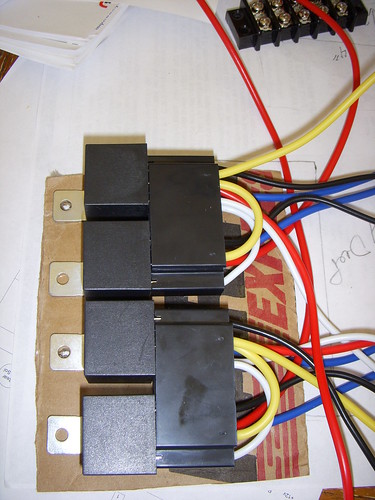
I made a metal plate from my template to mount the relays. The nut between the relays is attached to a stud I welded to the plate as a convenient grounding point.
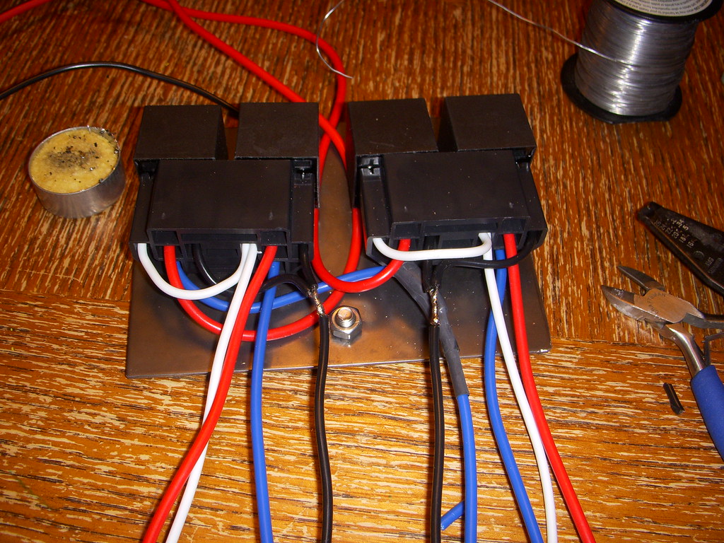
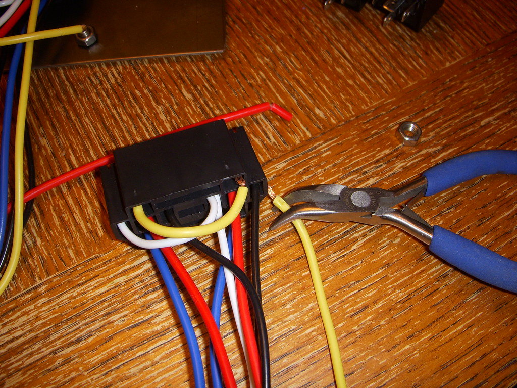
Not all the wires on the relay sockets are used, I made sure to ohm everything out and match the wires to diagram correctly, the worst case scenario would be wiring it wrong and back feeding the dash cluster. Keep in mind the dash indicators are turned on when you ground them. While the solenoid for the lockers need +12v to turn on. The colors on the schematic do not match the socket wire colors but the output numbers should.
The board prior to installation

The board fits very nicely in the factory location and the location makes it easy to run the wires through the firewall. I used nylon insert nuts so that I don’t have to worry about them backing out

I attempted to find a plug that would fit the D5 gray connector for the factory ECU so that I could simply plug my ARB relay board into it but I did not have much luck with that so I ended up soldering the connections together.

I purchased the factory rotary switch and the indicator lights from CDan. The wiring from the switch is already in place from the factory and just needed to be plugged in. The D5 connector ties this switch to the ARB relay board. The dash cluster has to be pulled out to install the indicator lights for the front and rear locker. The bulb sockets have masking tape over them from the factory that is easily removed.
The air compressor was installed in the front right side of the engine compartment. I had already used some of the space where the Slee backet mounts in the left rear so I opted to create my own bracket and use the two existing body screw inserts to bolt into.

I welded a sturdy bracket to mount in the location and used loctite on the bolt threads when installing.


The ARB compressor comes with a wiring harness and I salvaged most of this on the compressor side. On the control side I made several changes to integrate it a little cleaner into the factory system.
I removed the Fuse that comes with the compressor and replaced it with a Blue Sea Systems 40A weather resistant circuit breaker that I mounted on the top of the firewall.


I ran my control wires from the ARB relay board to the solenoids and the control wire for the compressor through the existing boot in the fire wall. On the right hand side of the engine compartment.

The solenoid control wires from the ARB relay board where then soldered into the ARB compressor harness to the Yellow and the Dk Green wires.
The wire from the compressor harness for the compressor relay was not long enough to make it from the front right side of the truck all the way back to the left side of the dash so it needed to have a wire soldiered onto it so it could be extended. I purchased a Used Toyota switch with the plug and wires off Ebay for $5, there are lot of switches available that will fit in the 80 series dash holes but I waited till I could get one with the plug and wires attached. The switch just needed a 12v source that is fed off Ignition switched power.

The system works great and so far has presented no issues.
The purpose of this project was to install ARB air lockers and have them integrated into the factory switch and dash indication. There are some other threads on this subject and I used that information to help get my start. Here is how I did it and maybe this information will help the next guy.
I started by researching the wire diagram for the factory locker system.

From that I created a diagram for replacement for the factory Diff Lock ECU.
I measured up the factory location of the ECU and determined that I could fit standard relays in exact same spot.
I created a cardboard template to build a metal plate to mount in the location.
I purchased dual relay sockets from Parts Express, these worked nicely to pair up the relay for the locker with the relay for the dash indicator light. The bolt studs for the factory ECU also line up very nicely with the relays fastening clip but the holes in the relay need to be widened to fit over the stud. I chose a relay with a metal clip so it would mount a little sturdier.
www.partsexpress.com
Relay P/N 330-079
Dual relay socket P/N 090-844
I made a metal plate from my template to mount the relays. The nut between the relays is attached to a stud I welded to the plate as a convenient grounding point.
Not all the wires on the relay sockets are used, I made sure to ohm everything out and match the wires to diagram correctly, the worst case scenario would be wiring it wrong and back feeding the dash cluster. Keep in mind the dash indicators are turned on when you ground them. While the solenoid for the lockers need +12v to turn on. The colors on the schematic do not match the socket wire colors but the output numbers should.
The board prior to installation
The board fits very nicely in the factory location and the location makes it easy to run the wires through the firewall. I used nylon insert nuts so that I don’t have to worry about them backing out
I attempted to find a plug that would fit the D5 gray connector for the factory ECU so that I could simply plug my ARB relay board into it but I did not have much luck with that so I ended up soldering the connections together.
I purchased the factory rotary switch and the indicator lights from CDan. The wiring from the switch is already in place from the factory and just needed to be plugged in. The D5 connector ties this switch to the ARB relay board. The dash cluster has to be pulled out to install the indicator lights for the front and rear locker. The bulb sockets have masking tape over them from the factory that is easily removed.
The air compressor was installed in the front right side of the engine compartment. I had already used some of the space where the Slee backet mounts in the left rear so I opted to create my own bracket and use the two existing body screw inserts to bolt into.
I welded a sturdy bracket to mount in the location and used loctite on the bolt threads when installing.
The ARB compressor comes with a wiring harness and I salvaged most of this on the compressor side. On the control side I made several changes to integrate it a little cleaner into the factory system.
I removed the Fuse that comes with the compressor and replaced it with a Blue Sea Systems 40A weather resistant circuit breaker that I mounted on the top of the firewall.
I ran my control wires from the ARB relay board to the solenoids and the control wire for the compressor through the existing boot in the fire wall. On the right hand side of the engine compartment.
The solenoid control wires from the ARB relay board where then soldered into the ARB compressor harness to the Yellow and the Dk Green wires.
The wire from the compressor harness for the compressor relay was not long enough to make it from the front right side of the truck all the way back to the left side of the dash so it needed to have a wire soldiered onto it so it could be extended. I purchased a Used Toyota switch with the plug and wires off Ebay for $5, there are lot of switches available that will fit in the 80 series dash holes but I waited till I could get one with the plug and wires attached. The switch just needed a 12v source that is fed off Ignition switched power.
The system works great and so far has presented no issues.

")


 Oh... on... THAT side...