24 volt 13BT glowscreen (1 Viewer)

This site may earn a commission from merchant affiliate
links, including eBay, Amazon, Skimlinks, and others.

Joined
Sep 28, 2004
Threads
157
Messages
1,997
Location
Norwich, VT
Arg! I've searched and read many threads and still can't find what I need!

I've got an '87 RHD JDM 24 volt BJ74 w/13BT and the PO had disconnected the glow screen system (truck was most recently living in Mexico but has moved to Vermont, USA)

As similar as these two climates are I supposed I ought to start planning ahead and get ready for some coldish starts....I intend to install a lower rad. hose 110 Volt coolant heater and maybe someday a Webasto or Espar, but I also think it would be nice to have the factory "superglow" glow screen working....I mean come on? Superglow! how cool is that????


yes..anyway....Once I get the superglow system sorted I intend to do the yellow wire NC momentary switch mod but before I do that.....Yes I'm coming to it...there is an actual question here.....

1) how do I connected these wires to the 2 terminals on the glow screen?

2) The glowscreen appears to have continuity between the 2 terminals (as per the FSM) are there other things I should check/review before I reconnect the glow screen?

I'd be most excited if I could get the system working without frying/damaging anything....

All advice and comments are most welcome!

Best,

Rob "stayalert" M

PS O looky...I apear to have learned how to make actual photos appear and not thumbnails!!!
glowscreen.jpg
 
based solely on the threads visible on the left post do these wires both go on the left post???
 
the two wires that I'm looking for the proper home for are one white, one blue

here's a view around the side of the glow screen with what appears to be an unused terminal.....Also just heard from PO - solely disconnected to reduce draw on batts when in warm climes.....
glowscreen2.jpg
 
Connect your two power wires to the terminals so that they connect to the large wires on the glow screen. I used a starter solenoid and a momentary switch.

9a3fe653.jpg

Thanks Capt. Is that showing one to each terminal???
 
Trying not to over think/beat this to death but I REALLY don't want to fry something (like the timer for example)

I have read everything I could find (I have no wiring diagram) but can't find confirmation on where to attach these two wires....

I have a large blue wire and a large white wire....These are the wires I need to connect....Does one go on each of the 2 terminals that point towards the batteries? Does it matter which (blue or white) is attached to which terminal????

Thanks for any help!!!!

Best,

Rob M
 
Here's a better picture....
photo-6.jpg
 
My screen is 24v, but in a 12v system. My example may not be the best to follow regarding which terminal gets which wire in a pure 24 system. They should be sandwiched in the terminal with the existing large wires that run to the sides of the grids.
 
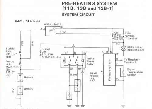
Are these pics useful?

13BTintakeHeater.jpg

13BTpreheat.jpg

:cheers:
13BTintakeHeater.jpg
13BTpreheat.jpg
 
Well I guess I'm pretty much an idiot because I've looked at those diagrams (from the manual that I have (in hard copy and downloaded) - I've tested the continuity but looking at the second diagram - I still don't know where to connect the blue wire and the white wire.:bang:
 
Well I guess I'm pretty much an idiot because I've looked at those diagrams (from the manual that I have (in hard copy and downloaded) - I've tested the continuity but looking at the second diagram - I still don't know where to connect the blue wire and the white wire.:bang:

You say that you have the manual in hard copy.....
Is there no wiring diagram in the back?
You should find the wire colors in that diagram.

Rudi
 
You say that you have the manual in hard copy.....
Is there no wiring diagram in the back?
You should find the wire colors in that diagram.

Rudi

The B,3B,11B,13B,13B-T Engine Repair manual that I have does not have wiring diagrams in the back.:confused:
 
The B,3B,11B,13B,13B-T Engine Repair manual that I have does not have wiring diagrams in the back.:confused:

Oh, that sucks.
Let's hope somebody else chimes in with that info.

Rudi
 
Hi Rob

I can see your problem.

I think the 13BT glowscreen wiring ... with colour codes ... should be in the back of the Oct 1984 Chassis & Body FSM 36262 but it isn't. (Toyota only shows glowplug systems there.)

This is what I get, when trying to remove the irrelevant stuff from the last diagram I posted:

13BTpreheat.jpg

(Maybe Rudi/BJ40green might like to comment on whether I've got it correct or not?)

Do you get any voltage on those wires when you're try starting your cruiser? If so exactly what happens and when?

:cheers:
13BTpreheat.jpg
 
Wow Many thanks for the effort!.....I will see what I can come up with, testing wise....If I get voltage for say 14 seconds and then it drops off maybe that will be a helpful clue.......

My manual is Mar, 1986 and doesn't have the wiring diagrams either...

I knew I was getting into a sort of odd/rare rig but I'm kinda surprised noone has a similar enough glow screen to take a look and share what wires go where....
 
Hi Rob & Tom,

Is it safe to say that those 2 studs are just connecting points?
In other words: that's the place where the glow screen wires meet the glow relay wires? Nothing more, nothing less.
If the answer is yes then we have to figure out which stud is low ohms en which one is a bit higher ohms.
Once we have that figured out we have to meassure which wire is pre glow and which one is after glow.

How am I doing so far?

Rudi
 
Wow Many thanks for the effort!.....I will see what I can come up with, testing wise....If I get voltage for say 14 seconds and then it drops off maybe that will be a helpful clue.......
My manual is Mar, 1986 and doesn't have the wiring diagrams either...
knew I was getting into a sort of odd/rare rig but I'm kinda surprised noone has a similar enough glow screen to take a look and share what wires go where....

Yeah. AFAIK that manual is supposed to cover the 13BT but Toyota seems to have forgotten it in the wiring section.

And the 13BT is such a popular engine that it surprises me that there's not people queuing up to submit photos of their connections.

Hi Rob & Tom,
Is it safe to say that those 2 studs are just connecting points?
In other words: that's the place where the glow screen wires meet the glow relay wires? Nothing more, nothing less.
If the answer is yes then we have to figure out which stud is low ohms en which one is a bit higher ohms.
Once we have that figured out we have to meassure which wire is pre glow and which one is after glow.
How am I doing so far?...Rudi

Sounds a good idea to me Rudi.

:beer:
 
Thanks guys!! Don't hold your breath though.....I have bit of work and some travel that will interfere with getting after this puzzle....

Best!

Rob M
 

Users who are viewing this thread

Back
Top Bottom