Which plugs should I be running - B, 2B, 3B, H and 2H diesels (1 Viewer)

This site may earn a commission from merchant affiliate
links, including eBay, Amazon, Skimlinks, and others.

Let me start by saying Thank You.. All of the information I get from Mud is so helpful without it I would never be as far along with this conversion. The project is a FJ60 conversion to diesel using a 2H and wire harness out of a HJ60 both of same year. The reason for the second thread is just putting it out their to be seen and possibly answered too.

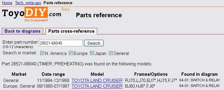
In the FSM I have looked at the HJ60 & HJ75 are listed. The 75 is 12 volt so I have been running with that set up. The per heat timer (28521-68040) Super Glow (82%sure) I need to buy glow plugs (19850-68050) hoping that I have the right part number for glow plugs to go with the pre heat timer I have.

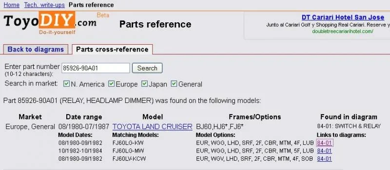
I have switched all of the relays form 24 volt to 12 V. With the exception of the dimmer relay( see photos). If anyone can give me a part number for a 12 volt dimmer relay that would help a lot . Or can the 24 volt be re work to 12 volt?

Thanks Again this all a learning curve for me.
Joe G
FJ601986

image-4031168990.webp


image-880538096.webp
 
..The project is a FJ60 conversion to diesel using a 2H and wire harness out of a HJ60 both of same year.

The per heat timer (28521-68040) Super Glow (82%sure)

Hi Joe.

Well my info supports your 82% surety so perhaps we can raise it to 85% or higher?

Looking at my info I see that relay as TIMER, PREHEATING and that it was used on Nov 84 to Oct 85 Australian-market HJ60 and HJ75 models - which I'd certainly expect to be 12V and certainly expect to have "superglow" preheating.


...I need to buy glow plugs (19850-68050) hoping that I have the right part number for glow plugs to go with the pre heat timer I have. ..

Yes. They are the correct plugs for 12V superglow as detailed in post #1 of this thread.

...I have switched all of the relays form 24 volt to 12 V. With the exception of the dimmer relay( see photos). If anyone can give me a part number for a 12 volt dimmer relay that would help a lot . Or can the 24 volt be re work to 12 volt?...

The 12V version of that appears to me to be 85926-90AO1 used on a 12V European FJ60 from Aug 80 to Nov 84.

(But prior to searching for this I never expected any 12V cruisers to use dimmer relays ... which shows how limited my knowledge is here.)

:cheers:
 
In addition to Toms research we can safely say that the TIMER, PREHEATING #28521-68040 is the correct one for your Super Glow system.
28521-68040 Super glow timer.webp

That head light dimmer relay which Tom mentioned has a small typo in it.
It's 85926-90A01 and not O1, thus zero one and not O one.
85926-90A01 dimmer relay.webp

As far as I can see it looks the same as the 24V one you showed us
85926-90A01 dimmer relay_price.webp

Hope this is helpful,

Rudi

28521-68040 Super glow timer.webp


85926-90A01 dimmer relay.webp


85926-90A01 dimmer relay_price.webp
 
lostmarbles, bj40green, I am nearly ready to install my 12HT (current have a 2H super glow with a glow light in dash, late hj47/45 diesel wire harness).

I have added the low oil pressure switch which the 2H has to the 12Ht as you just remove the bung from the 12Ht (goes in the same spot).

Now, there is 2 stages to the glow system, preheat & after glow, the 12HT only has a heat screen (12v)


1. Use from the 2H the Glow Plug Current Sensor aka "Sensor Relay" metal strip and connect it to the 12Ht heat screen

2. Then connect the preheat wire to the "Glow Plug Sensor " metal strip which in turn is connected to the 12HT heat screen.

3. The after glow wire (second wire) connect to the Glow Plug Current Sensor aka "Sensor Relay" as well.

So on first turn of the ignition key preheat sends 12 volts to the 12Ht heat screen for 1-5 secs, glow light on dash goes out, then on start the after glow then sends 12 volts for a further 5-10 secs? (not sure for how long) , the Sensor Relay" then send the signal back and the after glow turns off?


What problems do you see in this, can the Sensor Relay handle 12volts? and 12 volts back to the pre timer controller? as on the 2H there is a Resistor inline on the preheat & after glow wires so there is only 6 volts on reheat and roughly 9 volts on after glow? so will the Sensor Relay actually work faster and switch off the after glow as the volts will be 12 volts straight off?

Your thoughts on this?

I think you need to copy an intake heater preheat system for a 12H-T rather than try and adapt a 2H preheat system that was designed for use with six 6V plugs.

In other words, I don't think you can use either the 2H current sensor or the 2H preheat timer.

(You may be able to use the 2H relays, the 2H indicator light, and some of the 2H wiring though.)

:beer:
 
You can try the pre heater timer from the 2H and don't use pin 12.
Skip the Glow Plug Resistor and the Glow Plug Current Sensor.
Pin 1 is pre heat and pin 5 is after heat.

Here are both diagrams
2H super glow plus mom switch.webp


Pages from Engine_manual_2H_12HT_12Volt.webp


Personally I would opt for the 12H-T timer.

Rudi

P.s. Don't be mad at me if it doesn't work or starts smoking.
 
Hi Rudi, as I read the 12ht circuit nearly everything is the same as the 2H circuit, the only thing is pin 12. So if I don't connect pin 12 which is the wire that connects to the Glow plug sensor (which the 12Ht does not have installed anyway). The 2H glow plug relay's 1 & 2 lets 12 volts go to the glow plugs (which resistors drop down to 6 volts) are the same the as the 1 & 2 Intake relays from the 12ht which also let 12s volts go to the heat screen.

Is there any way of finding out the part numbers of the 2H glow plug relays to the part numbers of the 12HT intake relays. They well maybe the same because they both supply 12 volts? and the pre heat timer seems the same other than pin 12? wonder what the part number are for these as well?

PS. What's pin 6? and what is 0.5G that it connects to? In the image below the "Glow Plug Current Sensor" has two wires, I assume this is pins 12 & 6, so if I find out what pin 6 0.5G is I can connect it to the 12 volt line going to the heat screen?


GlowPlugCurrentSensorHJ75.webp
 
Last edited:
Long story but here we go.
Pin 6 is a detection point.
It detects how high (2H) or yes/no (12HT) the voltage is and reacts by cutting off the glow/pre heat time.

0.5 G is a fusible link. The wire size is 0.5 mm² and the color is Green.
You see that same symbol in the Glow Plug Current Sensor, but here the wiring is the fusible link.
A fusible link is a short piece of wire, 4 AWG sizes smaller than the wire it protects.
Ha... now it's getting confusing because the FL is in metric values and I'm talking AWG sizes. Never mind....

I think the bottle neck here is pin 6 but.... give it a try. Maybe it works, maybe not.

Rudi
 
Rudi, can I take the wire part off the "Glow Plug Current Sensor" use one end and connect it to the two "G" pin/wires that will go to the 12HT heat screen and the plug end then connect normally into the 2H wiring loom? I assume the other wire shown on the Current sensor is to pin 12?

Also can you check for me the following if you have time:-

"Is there any way of finding out the part numbers of the 2H glow plug relays to the part numbers of the 12HT intake relays. They well maybe the same because they both supply 12 volts? and the pre heat timer seems the same other than pin 12? wonder what the part number are for these as well?"

I've no idea about the spec's of that fusible link part so I wouldn't going that way.
You can take 4" of AWG20 (which is equal to 0.5mm²) and use that temporarily. Another option is to buy Fusible Link wire. The difference between regular wire and FL wire is the isolation. Regular wire melts and FL wire not.
More on Fusible Links in my thread: -► https://forum.ih8mud.com/threads/fusible-link-which-one-for-my-78-bj40.526232/

Glow Plug Relay for 2H engine 10/82 - 10/84 part# 28610-57011, 11/84 - 7/87 #28610-54090

Intake Heater Relay (in the parts list named as Glow Plug Relay) for 12HT #28610-57100

Timer 2H #28521-54021
Timer 12HT #28521-68070

Rudi
Thanks Rudi, interesting they are calling the 12ht relays - Glow Plug Relays, would be also interesting to see what the actual rating of the 12ht relays are against the 2h ones.

I tried to buy some fusible link wire here in Brisbane but none is available.

With your expertise can you tell me on the 'Glow Plug Current Sensor" on the 2H is the plus connection going to pins 6 & 12?

Also the wire part on this sensor I wonder if I can get away with using that?

PS. Also the glow plug resistors in the above diagram "28621" which do you think is connected to glow plug relay No 1, would this also be pre-heat and then glow plug relay No 2 which one and would this be after heat?

I don't understand what you want to accomplish with the "old" 2H parts. You don't need them.
All those parts are not polarity sensitive. Resistors, light bulbs, heater elements, glow plugs, they don't have a + or a - terminal.

Rudi
 
Fundamentally, my 2H circuit is the same as the 12Ht one, have two glow plug relays, one pre-heat one after-heat. Connect these two wires "G" to the 12ht heat screen. The 2 wires coming off my Glow Plug Current Sensor must be pins 6 & 12, disconnect pin 12 and get 0.5G fusible wire and connect it to the 2 wires ("G") that are connected to the 12ht heat screen connection - then plug the other end on the 0.5G fusible link into pin 6?

The only thing I need to find out is how much difference is in the preheat timer of a 12ht and whether it has a pin 12 but they just don't use it.
 
Rudi, is this green wire the 0.5G fusible link, its on both the 12 volt & 24 volt heat screen systems.

12htvaccumhoses.webp


imagesY5OUQGKT.webp


untitled.webp


PS. Rudi, this wire in the below image (black with red stripe) can you tell me what it connects too and what is it for?

IMG_1584.webp
 
The two timers may look the same but the internals and function is different.
The 2H timer measures the voltage drop (pin 6 and 12) over the Glow Plug Current Sensor.
The 12HT timer measures Yes/No voltage (pin 6) to the Intake Screen.
Ergo conclusio....... they are different.

The (2") Green wire in the center of the 3rd picture is the 0.5 G fusible link.

I don't know what that Black/Red wire is for. You need a wiring diagram to search for it.

Rudi
Hi Rudi,

Just managed to buy some fusible link wire colour coded as follows:-

Blue Fusible Link Wire 100 Amp
Black Fusible Link Wire 80 Amp
Yellow Fusible Link Wire 60 Amp
Red Fusible Link Wire 50 Amp
Green Fusible Link Wire 40 Amp

Can you tell me what amp rating was the Grey, Orange, Purple fusible link wire, I cannot find any info?

Ok, found something,

Brown is 50 amp
Grey is 50 amp
Orange is 40 amp
Purple still cannot find?
 
Last edited:
Hi Rudi,

Just managed to buy some fusible link wire colour coded as follows:-

Blue Fusible Link Wire 100 Amp
Black Fusible Link Wire 80 Amp
Yellow Fusible Link Wire 60 Amp
Red Fusible Link Wire 50 Amp
Green Fusible Link Wire 40 Amp

Can you tell me what amp rating was the Grey, Orange, Purple fusible link wire, I cannot find any info?

Ok, found something,

Brown is 50 amp
Grey is 50 amp
Orange is 40 amp
Purple still cannot find?

1. There is no (international) color code standard for fusible links. Every manufacturer uses his own color code.
Toyota color "purple" is 0.3 mm² or AWG22 which protects AWG18 wires.
I think we've had this discussion before in another thread.

2. A fusible link is NOT A FUSE !!!!
It protects a harness or loom from burning up. You can compare it with the weakest link in a chain. If the force is too big the weakest link will snap. So if you put a "weak link" on purpose in a chain you've reached your goal.
If you want a fuse....... use a fuse.
Because most people don't have a clue about electric stuff the manufactures decided to add a maximum Amp rating to their fusible links. So a "Red Fusible Link Wire 50 Amp" as you mentioned above would burn at 50 Amp or higher.
Well.... I have my doubts about that. But if the wires from and to that fusible link are a bigger size...... can you guess what happens??

The Toyota color code is:
Fusible Link..................Protects circuits with wire size
mm²..Color.......AWG...................mm².....AWG

0.3 P Purple.......22....................0.85......18
0.5 G Green.......20....................1.25......16
0.85 R Red........18....................2.0........14
1.0 GR Gray.......17....................2.63......13
1.25 B Black......16....................3.0........12
2.0 L Light Blue..14....................5.0........10
3.0...................12....................8.36........8

As you can see in this picture, the manufacturer color for 1.0 mm² is Orange where the Toyota color is Gray.
fusible link 2.webp


I wish you luck,

Rudi
 
Damn Rudi, if I was not confused before I am now? Ok, the 3 fusible links I am supposed to have at my battery connection are Red, Black & Purple. These are Toyota colour code, so can you tell me what amperage they would be?

Also the Green fusible link (Toyota) we have spoken about what amperage would that be?

By getting the amperage figures of the Toyota colour code I can use the fusible link wire I have purchased.

No, I can't give you the amperage because that doesn't work for me.

Strip 1/2" insulation from all the wires you have. You'll see that the core diameters are different
You'll need the wire with tiniest core to replace the 0.5Green link.
That's all I can say.

Rudi
 

Users who are viewing this thread

Back
Top Bottom