bj40green
Tssss, tssss
A lot of you don't like electric stuff and especially not complicated things like an external Voltage Regulator. So maybe it's time to explain how this black box with 3 or 6 wires works. It's really pretty simple.
A VR (Voltage Regulator) regulates the charging process of the alternator. Our mechanical VR's have only 3 positions.
Position 1. Full charge
The battery voltage is less than 13.6V.
Position 2. Trickle (or Half) charge.
The Voltage is 13.6V. The battery is now fully charged and needs only to be topped off.
Position 3. No Charge / the battery is full and more charging will damage (cook) the battery.
The Voltage is 14.4V (or between 14.4 and 14.8 depends on the factory setting aka "set point")
Here is the Toyota explanation from the FSM (Factory Service Manual)

I've "translated" the FSM diagram in this one which is easier to read and understand.
The left part of this diagram is the alternator, the right part shows the Voltage Regulator.
No matter if the VR has 3 or 6 wires, there is always a E, IGN and F wire/terminal.
The other 3 are N, L and B in case of a 6 wire VR. More about this later.
E = Earth / Ground
IGN = Voltage from the Ignition key (= battery voltage) aka "Sense".
This voltage is used to detect how high the battery voltage is.
F = Field. This voltage activates the alternator and controls the output voltage of the alternator.

Look at the VR part of the diagram. The heart of the Regulator is a 3 way switch that is activated by magnetism. Most people call this a relay which is in a way correct.
The switch is pulled closed in the top (1st) position by a spring.
The Voltage from the battery (passing the ignition key) goes directly to the F terminal. Therefore the alternator is activated to charge with full power. Note: The resistor is bypassed / overruled / shortened out.
When the voltage goes up, the coil of the switch is energized and builds up a magnetism that starts pulling the switch to the 2nd position.
When the battery voltage reaches 13.6V the coil is enough energized to actually pull the switch to the 2nd (open) position.
At this point the switch is open and the 10 Ω (ohm) resistor is now in series with the F terminal. The voltage to the F terminal and thus the alternator, is reduced to approx. 6 to 7V.
The output of the alternator is now decreased and the battery will be Trickled charged.
The battery voltage will continue climbing until the Voltage is 14.4V. At this point the coil is so much energized that it pulls the switch in the 3rd position.
When the switch is in the 3rd position the F terminal is grounded so the charging process is stopped.
Unfortunately (or on purpose by design, I haven't figured that one out yet) now the V ignition is also grounded via the resistor and this creates a lot of warmth and makes the VR feel pretty hot.
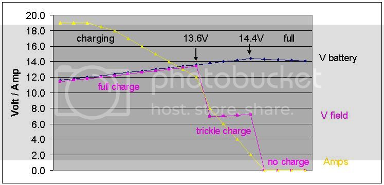
Here is the same story but now in a graphic.
Here are 3 pics with the different positions.
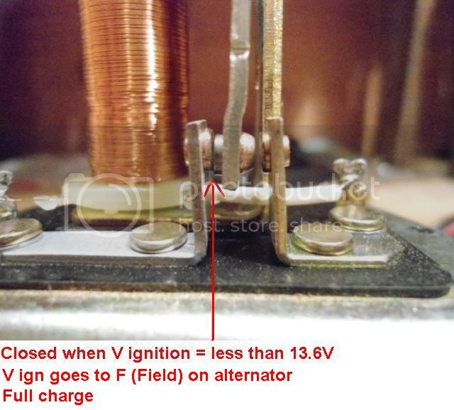
Full charge
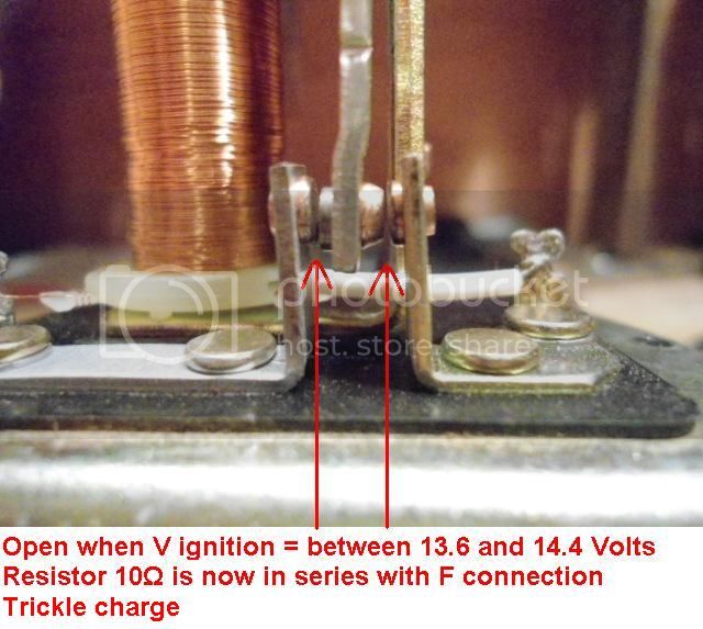
Trickle or Half charge
No charge / Battery is Full

I also made little movie so you can see it live!
Rudi
A VR (Voltage Regulator) regulates the charging process of the alternator. Our mechanical VR's have only 3 positions.
Position 1. Full charge
The battery voltage is less than 13.6V.
Position 2. Trickle (or Half) charge.
The Voltage is 13.6V. The battery is now fully charged and needs only to be topped off.
Position 3. No Charge / the battery is full and more charging will damage (cook) the battery.
The Voltage is 14.4V (or between 14.4 and 14.8 depends on the factory setting aka "set point")
Here is the Toyota explanation from the FSM (Factory Service Manual)

I've "translated" the FSM diagram in this one which is easier to read and understand.
The left part of this diagram is the alternator, the right part shows the Voltage Regulator.
No matter if the VR has 3 or 6 wires, there is always a E, IGN and F wire/terminal.
The other 3 are N, L and B in case of a 6 wire VR. More about this later.
E = Earth / Ground
IGN = Voltage from the Ignition key (= battery voltage) aka "Sense".
This voltage is used to detect how high the battery voltage is.
F = Field. This voltage activates the alternator and controls the output voltage of the alternator.

Look at the VR part of the diagram. The heart of the Regulator is a 3 way switch that is activated by magnetism. Most people call this a relay which is in a way correct.
The switch is pulled closed in the top (1st) position by a spring.
The Voltage from the battery (passing the ignition key) goes directly to the F terminal. Therefore the alternator is activated to charge with full power. Note: The resistor is bypassed / overruled / shortened out.
When the voltage goes up, the coil of the switch is energized and builds up a magnetism that starts pulling the switch to the 2nd position.
When the battery voltage reaches 13.6V the coil is enough energized to actually pull the switch to the 2nd (open) position.
At this point the switch is open and the 10 Ω (ohm) resistor is now in series with the F terminal. The voltage to the F terminal and thus the alternator, is reduced to approx. 6 to 7V.
The output of the alternator is now decreased and the battery will be Trickled charged.
The battery voltage will continue climbing until the Voltage is 14.4V. At this point the coil is so much energized that it pulls the switch in the 3rd position.
When the switch is in the 3rd position the F terminal is grounded so the charging process is stopped.
Unfortunately (or on purpose by design, I haven't figured that one out yet) now the V ignition is also grounded via the resistor and this creates a lot of warmth and makes the VR feel pretty hot.
Here is the same story but now in a graphic.

Here are 3 pics with the different positions.
Full charge

Trickle or Half charge

No charge / Battery is Full

I also made little movie so you can see it live!
Rudi
Last edited:
")


")