Voltage Regulator (ext.) / How it works (1 Viewer)

This site may earn a commission from merchant affiliate
links, including eBay, Amazon, Skimlinks, and others.

I think that this is the one you're looking for.
View attachment 778604

Note: There are 2 White/Blue (W/L) wires. Don't mix them up!
The thin one is between the N terminals.
The thick one is between the B terminals and continues to the fusible link(s) at the battery.

Rudi

Best of the Best man, Rudi.

This morning hook up the battery back on and turn the key to ON position, check the black with yellow strip wire (BY) on the regulator IG connector terminal has no power... trace it back to the engine fuse box and pushing the Engine fuse out put terminal with my volt meter cable tip and hear a clicking like a relay is energizing some where.... the fuse is sitting there but due to more than 30 years old truck and slowly build up dirt on the fuse contact surface that preventing full 12 volt flow through the out put terminal.
I go through every single fuse holder and clean with round file to shine them again, now has 12 volt on the regulator IG terminal again... wow!.. that is cool......
The truck charging system is fully functioning the way it should be now, very awesome....... :clap:
Thanks for your help, diagrams and great info. this is should be the BEST thread for some one that has the same issue problems......
Thanks again....

Charly
 
Last edited:
Hi Charly,

Glad to be of any help. Another problem solved. :bounce::bounce2:

Rudi
 
2 reasons for overcharging

There are 2 possibilities for overcharging when the Voltage Regulator is defective.

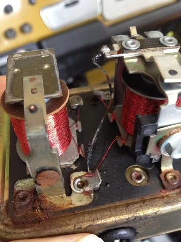
1. The regulating contacts are stuck together. When this is the case the Regulator can't open up so that the Resistor comes in series with the F terminal on the Alternator to reduce the charging. The VR is sending full power to the alternator and thus will the alternator not be limited in its output.
VR contacts.JPG
This is easy to fix. Open the contacts and clean them.

2. The "regulating coil" that activates the contact points is "cooked/fried/burned"
The effect is the same as in #1. The contact points will not (and shall never) open up any more.
Picture courtesy of Pearly
Pearly.jpg

Picture courtesy of Peterman
Peterman.jpg
This is not fixable. Time to buy a replacement.

Rudi
Pearly.jpg
Peterman.jpg
VR contacts.JPG
 
Hi Rudi, great works and very good explainations.
I' have a little question: i have a 12-ht 24volt (i'm in Italy and so european version), in this configuration, two 12v batteries in series, the VR read the voltage of one battery (which of the two?) in order to work properly and send from 27 to 29 V to the batteries? If I have a little overcharging, 29,5V, do yu think is a bad VR or have to check a bad ground or...??
Thank's for the halp and for the very useful tread you have done!!!
Pippi
 
Hi Rudi, great works and very good explainations.
I' have a little question: i have a 12-ht 24volt (i'm in Italy and so european version), in this configuration, two 12v batteries in series, in order to work properly and send from 27 to 29 V to the batteries? If I have a little overcharging, 29,5V, do yu think is a bad VR or have to check a bad ground or...??
Thank's for the halp and for the very useful tread you have done!!!
Pippi

.....the VR read the voltage of one battery (which of the two?)

The VR reads from the high one. Thus from the 24V side.
29.5V is a bit on the high side but it's not "overcharging" as in "cooking the battery".
Maybe you can check with a different Voltmeter and compare the readings.
If the reading is the same and you're not comfortable with it, you can try to lower the voltage by bending the regulator arm as described in posting #13.

Ciao,

Rudi
 
Thanks for the write up! So if your VR died in the middle of nowhere could you wire the F terminal on your alternator to battery voltage to make it home? Would you have to cycle the connection on and off to prevent over charging?

Smart thinking Oregon! In theory you're right but............. there's always a but. If you connect F to the battery, the alternator keeps charging and charging 15V....16V.....17V.....18V..... do I need to go on?
If the VR dies, most of the time you can make it home on the battery. If the battery is in good shape you can drive a few hours before the ignition dies by starvation of voltage.
For DIESELS: Up to DEC '78 diesels can run with no battery at all.
From Jan. '79 the diesels are equipped with an EDIC system which needs power same as the ignition system for gassers.

If the battery is not in a good shape you can try this;
Connect F to +Batt and drive with low RPM's (around 1000 - 1200) and your headlights on. This way you keep the Voltage a bit under control. The alternator starts charging above 800 RPM.
NOTE: I don't recommend this method, but if you're in the middle of nowhere....

EDIT: keep a spare in your toolbox, better.... mount the spare on the inside fender.
View attachment 773423

Rudi

Rudi,

Sorry to bring this topic back up, but I've got a quick question. I understand that Oregon's solution could result in overcharging the battery. Might a better approach be connecting F to the battery via a 10 ohm (or even larger) resistor, thus reproducing the 'trickle charge' mode of the alternator? If so, to take it one step further, might it be easier to just jump B and F at the alternator with said resistor?

Thanks for taking the time to do this write up!
 
Very good thinking! :clap:
That's exactly the same situation as the "trickle charge" position.
It's even easier if you mount the resistor in an identical VR connector.
Ign to F in the connector. That way the circuit is off when you turn the engine off.
Just unplug the VR and plug in the 10 ohm resistor.

Rudi

Ah...that's a perfect solution. I'll make up a VR bypass plug and throw it in the trail tool bag.

Thanks!
 
Sorry for the Hi-Jack, BJ40green, but how do you like living in Costa Rica ? I'll delete this post if you don't want non-tech in this thread ...
 
Ah...that's a perfect solution. I'll make up a VR bypass plug and throw it in the trail tool bag.

Thanks!

Please post a pic of your "finished product".

Rudi
 
Sorry for the Hi-Jack, BJ40green, but how do you like living in Costa Rica ? I'll delete this post if you don't want non-tech in this thread ...

Hi Spike, I (we) love it here. Have been here for more then 13 years. Never been back to Holland. Nice weather, friendly people, lots of Cruisers.
If you have specific questions, send me a Email not a PM.

Rudi
 
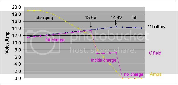
I've added this graphic diagram to my first post for a better "visual" understanding of the charging process.


Rudi
 
Thanks Rudi for all your help!
But now I'm completely confused. Here is what I have on a 1980 FJ40.


I only have 2 wires that actually run to that Alt. The Black/Yellow and the White/Blue


I did however find the lamp wire that was unhooked, that should from your schematics, should be hooked up to the alt above the blk/yellow. I also found a blk wire that had a fuse on it along with a wht/blue wire. Both of these are unhooked.:doh:
This is what baffles me:
Note: There are 2 White/Blue (W/L) wires. Don't mix them up!
The thin one is between the N terminals. (Not connected and has a fuse on it))
The thick one is between the B terminals and continues to the fusible link(s) at the battery.(On mine goes straight to the Battery)

My ammeter doesn't work and the alt isn't charging the battery! See my dilemma :bang:
 
Hi Techi,

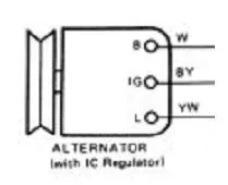
What you have there is a Alternator with IC regulated internal Voltage Regulator.
In this case the VR is on top of your alt. The markings on the VR are for the connections inside. S = Sense, L = Lamp and F = Field.
Yours is the same as this one
2wire_alternator.jpg

In a wiring diagram it looks like this
BJ60 with IC regulator.JPG

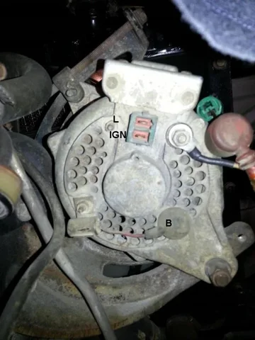
I've edited your pic with the corresponding terminal letters.
20130916_214829_text.jpg

The White/Blue goes to the B terminal and ends up at the battery (preferable with a fusible link in series).
I think yours is hooked up to the wrong stud.
Black/Yellow goes to the IGN terminal. This wire is "hot" when the IGN key is in the "on" position and activates the alternator.
White/Yellow (or maybe a single Yellow) goes to the L terminal and is for the "NO CHARGE" light on the dash. There can be a diode in series.

If your alt is not charging, check for voltage on the Black/Yellow wire when the key is in the "on" position. There should be the same voltage as the battery voltage. If not.... trace the wire back to the fuse block until you have voltage.

With Black/Yellow and the White/Blue wires connected it should work.

Rudi
BJ60 with IC regulator.JPG
2wire_alternator.jpg
20130916_214829_text.jpg
 
Hey Rudi thanks for the quick reply.

After looking at the alt...Where the wht/blue land is a letter "B" the pic is a little blurry for you to see, but there is also a "B" in the location you marked.

But I did check the voltage from on the black/Yellow...Its 1-1.5v less than the battery voltage while the key was in the "ON" position. Any Ideas? I'll have more time tomorrow evening to look at it.

Thanks again for your help!
 
This is a super write-up! Had I seen this many months ago, I may have been able to avoid buying a new VR(but I did anyway) I also got another one just as recommended. I would vote to keep it in the toolbox in a static-free bag for when the installed one fails----
 
Hey Rudi thanks for the quick reply.

After looking at the alt...Where the wht/blue land is a letter "B" the pic is a little blurry for you to see, but there is also a "B" in the location you marked.

But I did check the voltage from on the black/Yellow...Its 1-1.5v less than the battery voltage while the key was in the "ON" position. Any Ideas? I'll have more time tomorrow evening to look at it.

Thanks again for your help!

1-1½V less is OK. It means that there is a current draw. You also lose a bit of voltage "en route" so to say.
It doesn't hurt to move the White/Blue to the other terminal.
What is the history here? Did it work before? When did it stop working? Why is that L wire disconnected? Did you inherit this from a PO? What?

Is that White/Blue wire unmolested?
the White/Blue......(On mine goes straight to the Battery)

If that wire goes directly to the battery, the Ammeter will never show the Charge current. I suspect that this is an Alternator modification (a higher output alt.) and that the PO changed the wiring to bypass the 30-0-30 Ammeter in case the current is higher than 30Amps.

WHOOOAAAA, wait a minute..... yours is a 1980, right? So you have the 0-50-0 Ammeter. The famous Ammeter that shows nothing due to a design flaw in that circuit.

Doesn't matter in the end. If that White/Blue goes directly to the battery it should work. Did you ever check the voltage while the truck was running or do you suspect it isn't charging because the Ammeter shows nothing?

Another question is... do you have the "NO CHARGE" light on your dash?

A lot of questions, but we'll figure it out.

Rudi
 
What is the history here? Did it work before? When did it stop working? I bought the 40 a few months back, I'm truly not sure if it worked correctly or not. I noticed it the other night after driving it around and then losing battery power. Thats when the hunt began.Why is that L wire disconnected? Did you inherit this from a PO? What?Yes it was like that from the PO. I just want it to be right. So I can take the next steps and purchase or not purchase parts if it's wrong.

Is that White/Blue wire unmolested?Well, this is truly a good question. The pic below shows a splice of another wht/bl, bl/red and the wht/bl that head to the battery, to me it looks like a factory crimp under the tape, but I'm not as knowledgeable on such.


If that wire goes directly to the battery, the Ammeter will never show the Charge current. I suspect that this is an Alternator modification (a higher output alt.) and that the PO changed the wiring to bypass the 30-0-30 Ammeter in case the current is higher than 30Amps.

WHOOOAAAA, wait a minute..... yours is a 1980, right? So you have the 0-50-0 Ammeter. The famous Ammeter that shows nothing due to a design flaw in that circuit.

Doesn't matter in the end. If that White/Blue goes directly to the battery it should work. Did you ever check the voltage while the truck was running or do you suspect it isn't charging because the Ammeter shows nothing?Yes and it was low like a trickle charge, never above 9-10v, I figured the ammeter was never good, since it never moved and then I found this thread:)

Another question is... do you have the "NO CHARGE" light on your dash?There wasn't one when I got it! but the light socket is out under the hood and connects to the wire in the pic below, the other end was taped by the alt.


A lot of questions, but we'll figure it out. No worries, I really enjoy tinkering with it anyways....I find it relaxing:bang:;)

Rudi[/QUOTE]
 
Wow, that's a little mess you have there, but first let's clean up a few things.
1. Bl is that Black or Blue? I assume you mean Blue? In that case your text make sense.
2. You are missing the fusible link to the battery.
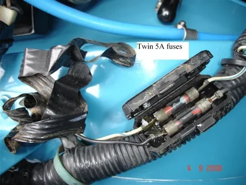
3. The double fuse for protecting the Ammeter should look like this.
Photo: Lostmarbles
Ammeterfuses2.jpg

4. The Ammeter reading is created by this little fusible link which I assume is also missing due to some PO hack job.
Photo: Lostmarbles
FusibleLink.jpg

5. That "splice" with the two White/Blue and the Blue/Red is not factory.
That Blue/Red wire should come from the heater fuse and is also the power for the gauge cluster. Looks like the PO made a bypass to get power directly from the battery.

You can find more info on the Ammeter and circuit in my thread: Clusters, Gauges & Odo meters and starts on page #4 at post #75.

Do you have a FSM (Factory Service Manual) with a wiring diagram?
What do you want? Just get it working or back to original with the fusible link and so on?

Rudi
Ammeterfuses2.jpg
FusibleLink.jpg
 

Users who are viewing this thread

Back
Top Bottom