.
.
Install of a Pro Comp 14" aux fan (#PC-2053 S), Derale relay (#16763), wired through the A/C pressure switch (no manual switch yet)
Parts Needed:
Pro Comp Fan (#PC-2053 S) + mounting kit
Derale Relay (#16763)
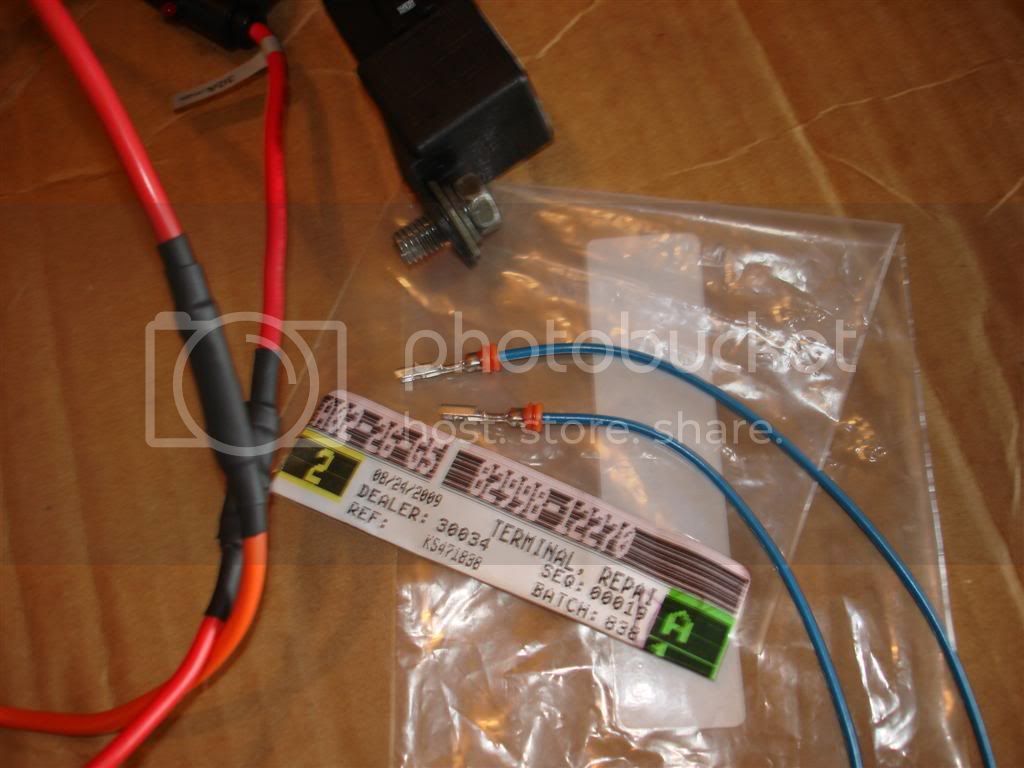
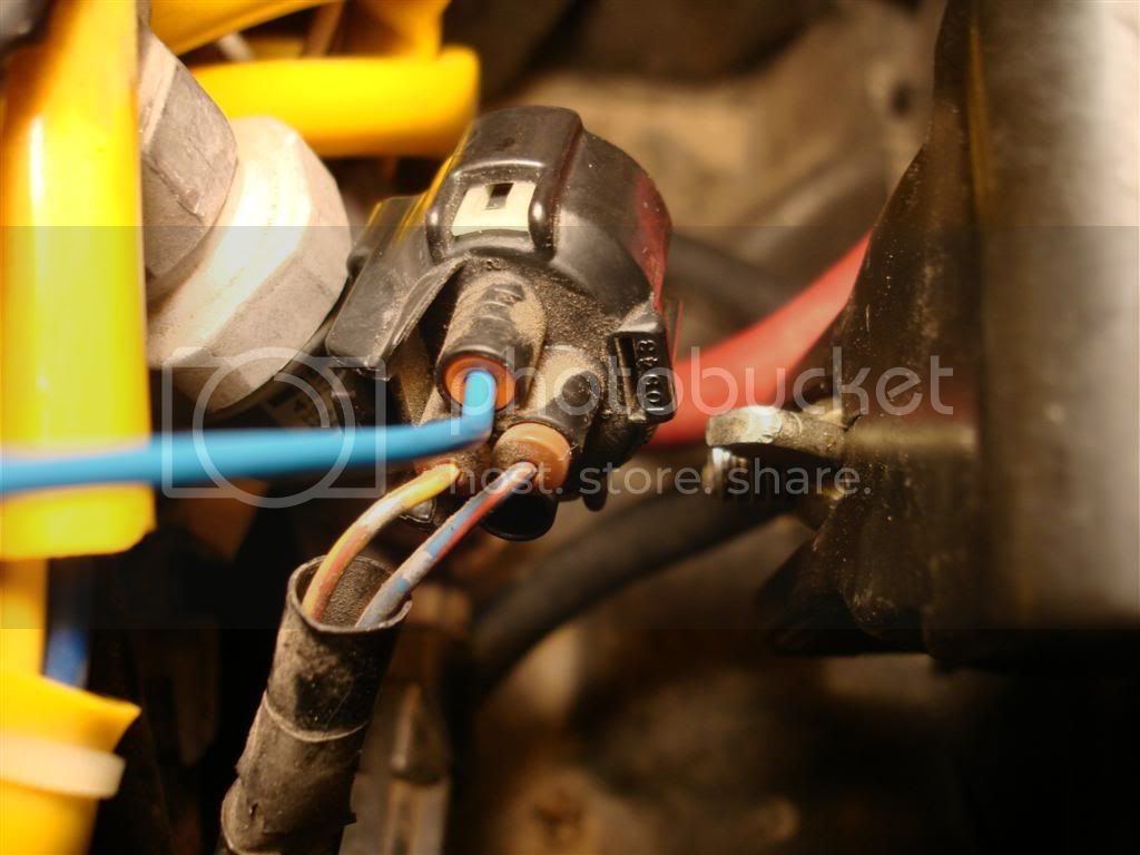
2 Toyota pig tails/terminals (2x 82998-12270)
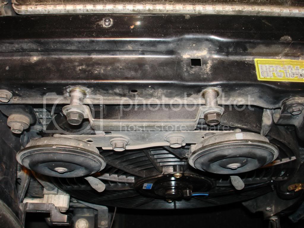
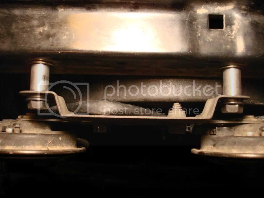
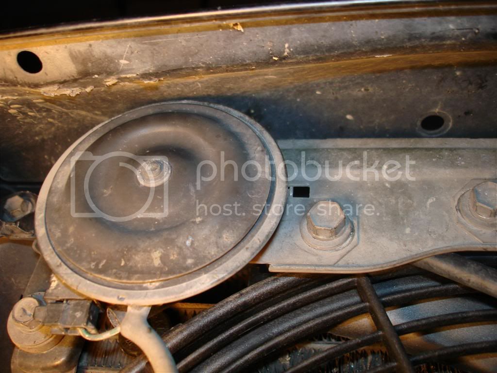
Appropriate wire, connectors, shrink tubing, in-line fuse, split loom, zip ties, spacers for horn bracket if desired, etc. etc.
Let me start by saying I consider myself a 1 person...Maybe border lining on the 2 stage...I envy those that have done this install and stated it was a piece of cake and took them no time at all...
I won't admit how long it took me to complete this but it wasn't just a couple hours - add in a few hours + typing this up and adding pictures. There is a reason I'm not a mechanic and don't do this for a living...Several times during the install I wished I had just ponied up the $$ for the JDM fan that is apparently a breeze to at least install...I imagine the wiring up portion would be the same regardless. So, choose wisely depending on your situation.
I decided to document this install because it wasn't "easy" for me like it seemed to be for so many others so if there are others out there like me, hopefully this will help. I did a lot of searching and did find a few threads that helped me here and there, but nothing conclusive start to finish. Also, this particular setup seems to be pretty popular lately and while this write up might help on other fans/relays, it is specific to the 14" Pro Comp fan (#PC-2053 S) and the Derale relay (Derale part #16763). I think many have been buying this setup (like I did) off ebay from seller northcoastperf.
This will almost be a step by step by step so hopefully I don't bore everyone to tears (or laughter) - My suggestion is to read through all of the steps to see what I did wrong/learned after the fact so you can avoid some of my missteps that just ate up more install time
FAN PREP
Step 1:
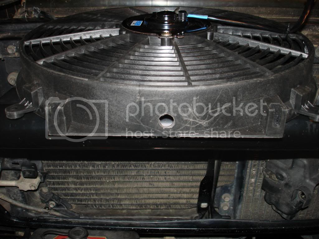
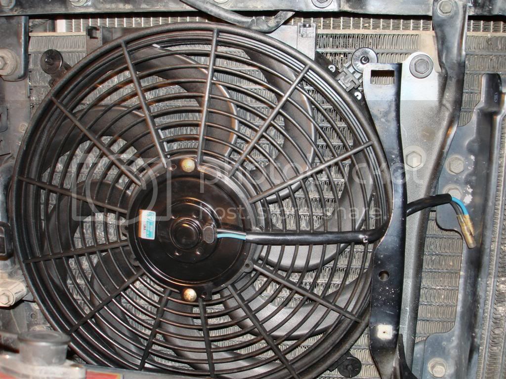
Flip the fan blade and check for plug polarity...
The Pro Comp fan comes as a "puller" fan and it needs to be converted to a pusher (otherwise you will just waste a bunch of your time adding a fan that won't help ). You convert the fan by flipping the fan blade (take off the nut, flip the blade, reattach nut) and then checking polarity of the plugs so the fans pushes air out the back vs. out the front (puller). In my case (and I imagine every case on this particular fan) the black lead on the fan became my + lead and the blue lead was my - lead. I marked the plugs with a + and - so I didn't have to remember later. I bench tested the fan operation to make sure it worked and to make sure it was "pushing" air with the above changes.
Step 2:
Drill a hole in the bottom of the fan (if desired/required) to drain water. Unless you are positive which way you will orient your fan, this is a step for later in the install so don't forget.
Step 3:
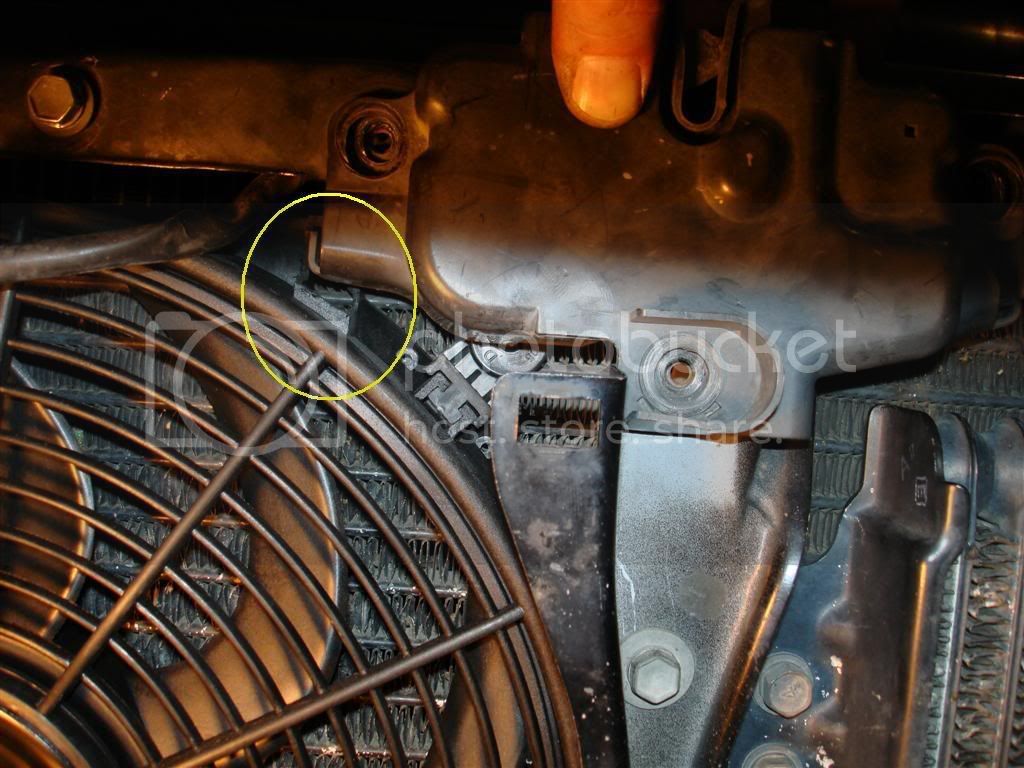
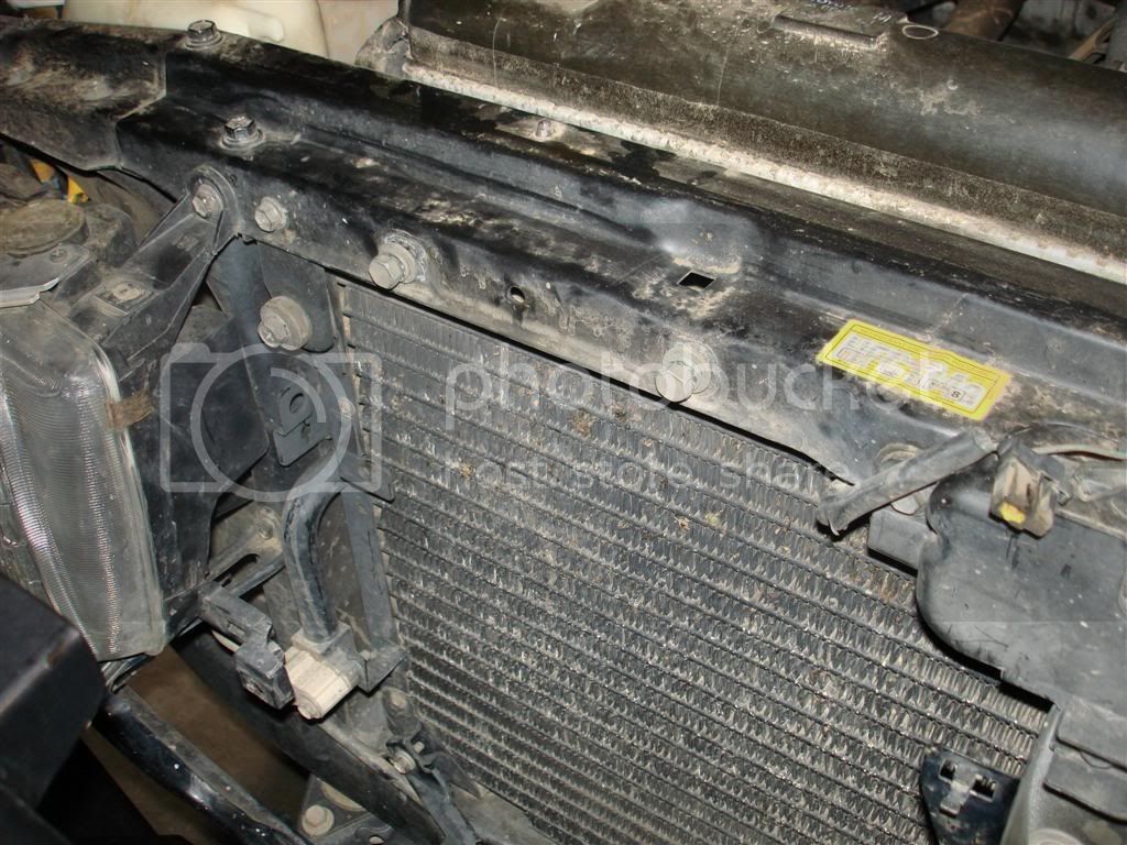
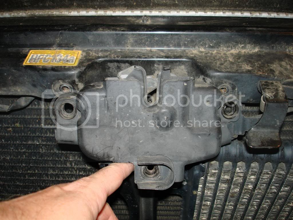
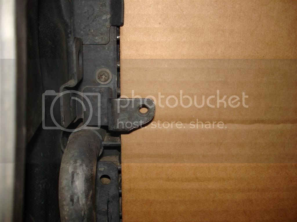
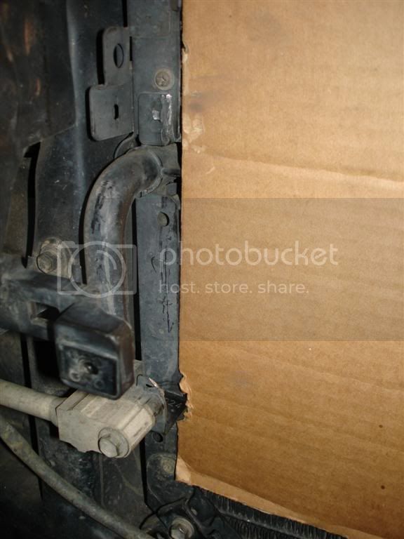
If required, trim/clearance one of the fans mounting tabs that may/will interfere with the hood latch. Again, unless you are positive which way you will orient your fan, this is a step that may be required later in the install so don't forget.
(cont)
.
Install of a Pro Comp 14" aux fan (#PC-2053 S), Derale relay (#16763), wired through the A/C pressure switch (no manual switch yet)
Parts Needed:
Pro Comp Fan (#PC-2053 S) + mounting kit
Derale Relay (#16763)
2 Toyota pig tails/terminals (2x 82998-12270)
Appropriate wire, connectors, shrink tubing, in-line fuse, split loom, zip ties, spacers for horn bracket if desired, etc. etc.
Let me start by saying I consider myself a 1
person...Maybe border lining on the 2 stage...I envy those that have done this install and stated it was a piece of cake and took them no time at all...I won't admit how long it took me to complete this but it wasn't just a couple hours
- add in a few hours + typing this up and adding pictures. There is a reason I'm not a mechanic and don't do this for a living...Several times during the install I wished I had just ponied up the $$ for the JDM fan that is apparently a breeze to at least install...I imagine the wiring up portion would be the same regardless. So, choose wisely depending on your situation.I decided to document this install because it wasn't "easy" for me like it seemed to be for so many others so if there are others out there like me, hopefully this will help. I did a lot of searching and did find a few threads that helped me here and there, but nothing conclusive start to finish. Also, this particular setup seems to be pretty popular lately and while this write up might help on other fans/relays, it is specific to the 14" Pro Comp fan (#PC-2053 S) and the Derale relay (Derale part #16763). I think many have been buying this setup (like I did) off ebay from seller northcoastperf.
This will almost be a step by step by step so hopefully I don't bore everyone to tears (or laughter) - My suggestion is to read through all of the steps to see what I did wrong/learned after the fact so you can avoid some of my missteps that just ate up more install time
FAN PREP
Step 1:
Flip the fan blade and check for plug polarity...
The Pro Comp fan comes as a "puller" fan and it needs to be converted to a pusher (otherwise you will just waste a bunch of your time adding a fan that won't help
). You convert the fan by flipping the fan blade (take off the nut, flip the blade, reattach nut) and then checking polarity of the plugs so the fans pushes air out the back vs. out the front (puller). In my case (and I imagine every case on this particular fan) the black lead on the fan became my + lead and the blue lead was my - lead. I marked the plugs with a + and - so I didn't have to remember later. I bench tested the fan operation to make sure it worked and to make sure it was "pushing" air with the above changes.Step 2:
Drill a hole in the bottom of the fan (if desired/required) to drain water. Unless you are positive which way you will orient your fan, this is a step for later in the install so don't forget.
Step 3:
If required, trim/clearance one of the fans mounting tabs that may/will interfere with the hood latch. Again, unless you are positive which way you will orient your fan, this is a step that may be required later in the install so don't forget.
(cont)

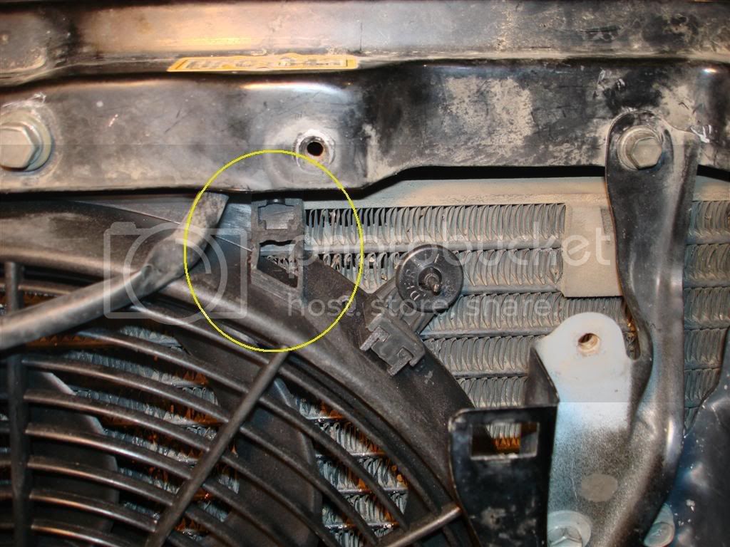
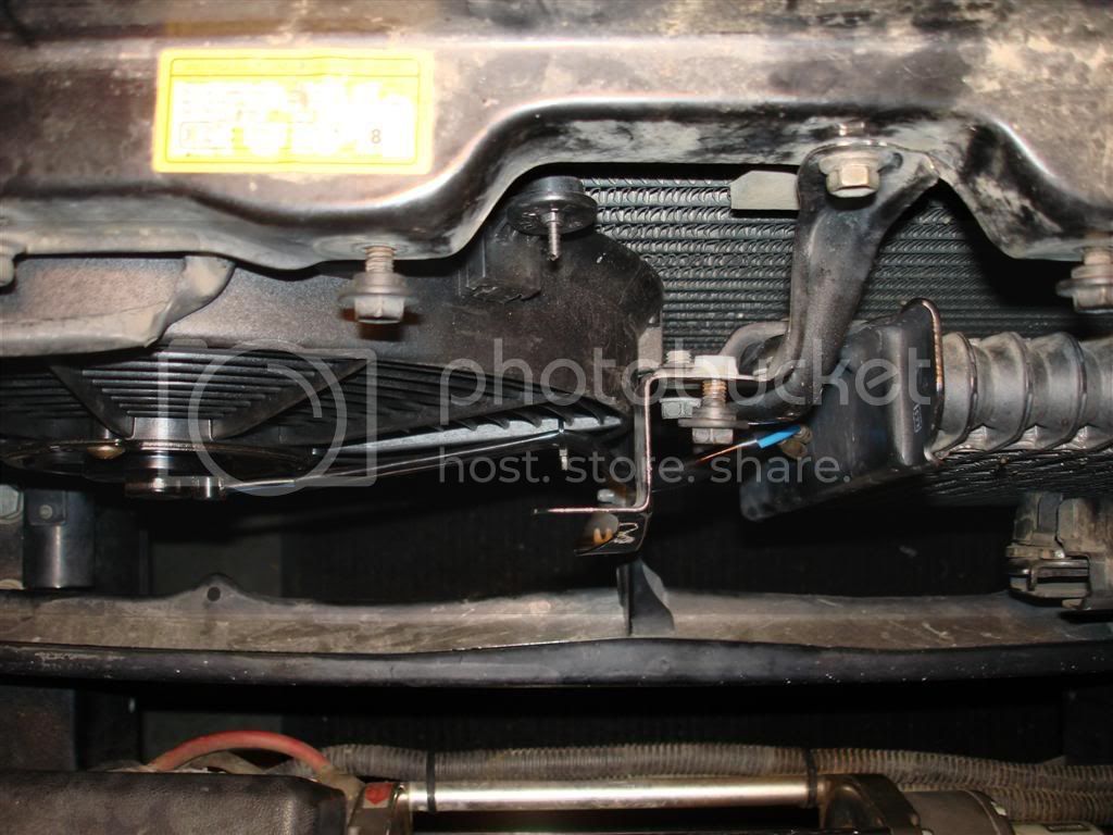


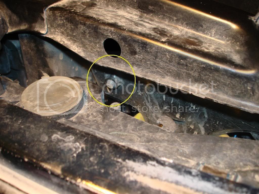
") - I put both the fan ground and the pressure switch ground into one ring terminal, crimped, and shrink tubed them (put the shrink tube on before crimping on the ring terminal
- I put both the fan ground and the pressure switch ground into one ring terminal, crimped, and shrink tubed them (put the shrink tube on before crimping on the ring terminal  ). Then I routed those to the existing DS fender chassis ground next to the battery tray and bolted it down.
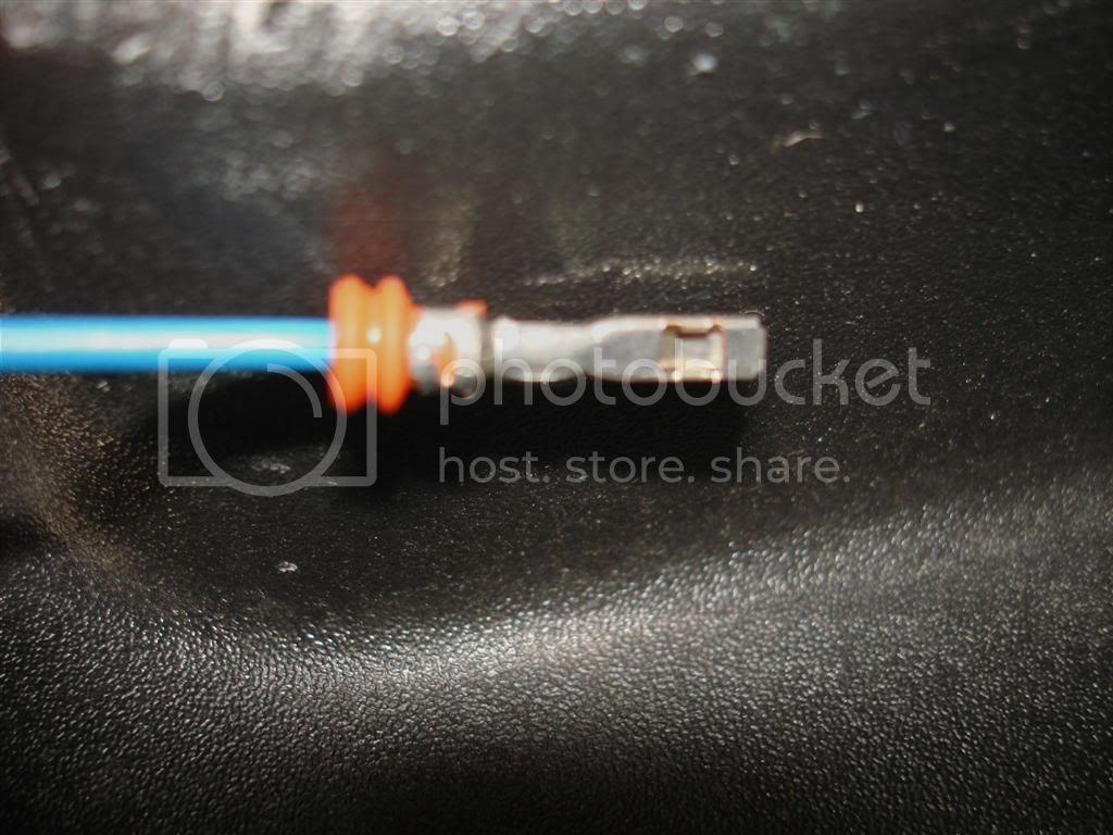
 According to the relay instructions the "Green Wire (pin 86) is: Optional - Attach to the Positive lead from the A/C clutch. This will allow you to turn on the fan every time the A/C is turned on". Well, seems like I can use this lead to wire up to an in cab switch but maybe the pressure switch grounding would interfere with this somehow.
 - I was extremely pleased to hear that fan come on after all that effort. I've only driven the truck a couple times. Once to work with the A/C off and I never noticed the fan coming on and it didn't run after I shut the truck off. On the way home from work I had the A/C on (low) and although I never heard/noticed that the fan came on during the drive, it was on when I pulled into the driveway and it ran after the truck was turned off for ~30 seconds.
 - If you see any errors/problems let me know so I can keep the original post accurate

 at the next after club meeting "meeting"
