
How long does it take for the mold to set up before you can pull them??
Navigation
Install the app
How to install the app on iOS
Follow along with the video below to see how to install our site as a web app on your home screen.
Note: This feature may not be available in some browsers.
More options
Style variation
You are using an out of date browser. It may not display this or other websites correctly.
You should upgrade or use an alternative browser.
You should upgrade or use an alternative browser.
improving flow for the 3FE’s top end
- Thread starter RockDoc
- Start date
This site may earn a commission from merchant affiliate
links, including eBay, Amazon, Skimlinks, and others.
- Thread starter
- #62
How long does it take for the mold to set up before you can pull them??
It's supposed to be 16 hours, but I found them still a bit tacky at that point. A couple more hours with a space heater blowing on the head took care of that (the instructions say something about heating after cure to drive out moisture and alcohol that are by-products of the reaction).
RocDoc you are crazy for doing all this work but hopefully something extremely useful will come of it. Keep on posting more pics, I love seeing what my engine looks like on the inside.
- Thread starter
- #64
The Good Stuff
Oh boy, have we got some good bits to show tonight.
Some good news and some bad news.
The bad: Pam spray isn't an effective release agent for separating 2 pours of silicone. It does, however, keep the silicone from taking on a rusty/stained appearance (note the difference between the runners and the CCs)
The good: it doesn't matter, cause the moulds came out as one piece!! Also, I believe I am now qualified for a job in a dildo factory
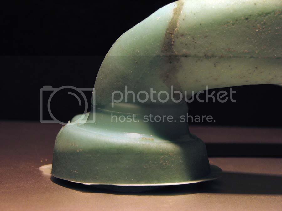
Here are a few shots of the 3 moulds together. You can see how the intake runner for cyl #2 (and its mirror image #5) comes in at a right angle to the elongation of the combustion chamber. This means that when the bulk of the intake flow comes in across the valve, it is directed straight at the wall of the chamber. The intake runner for #6 (mirror of #1) sweeps in at much more of an angle, and the intake flow is directed a bit more towards the open portion of the combustion chamber. Looking only at this geometry, #6/#1 should flow the best. Cylinder #4 (mirror #3) is intermediate and I chose it to do most of the modeling, so I moulded both the intake and exhaust runners. Don't mind the messy base of #6, I ran out of silicone, and tried to fill in a bit with trimmed scraps from the first pour.


Oh boy, have we got some good bits to show tonight.
Some good news and some bad news.
The bad: Pam spray isn't an effective release agent for separating 2 pours of silicone. It does, however, keep the silicone from taking on a rusty/stained appearance (note the difference between the runners and the CCs)
The good: it doesn't matter, cause the moulds came out as one piece!!
Also, I believe I am now qualified for a job in a dildo factory Here are a few shots of the 3 moulds together. You can see how the intake runner for cyl #2 (and its mirror image #5) comes in at a right angle to the elongation of the combustion chamber. This means that when the bulk of the intake flow comes in across the valve, it is directed straight at the wall of the chamber. The intake runner for #6 (mirror of #1) sweeps in at much more of an angle, and the intake flow is directed a bit more towards the open portion of the combustion chamber. Looking only at this geometry, #6/#1 should flow the best. Cylinder #4 (mirror #3) is intermediate and I chose it to do most of the modeling, so I moulded both the intake and exhaust runners. Don't mind the messy base of #6, I ran out of silicone, and tried to fill in a bit with trimmed scraps from the first pour.
Last edited:
- Thread starter
- #65
Some detail of #2:
General shots


Some detail of the valve seat area. Note the relationship between the insert, the machined area immediately behind, and the raw cast iron further behind. Smoothing out these transitions should help flow.


Some detail of the valve guide guide area. Again, things can be streamlined some, and cut back into the casting on either side of the valve guide to keep the cross-section of flow from changing so drastically as it encounters the guide.


General shots
Some detail of the valve seat area. Note the relationship between the insert, the machined area immediately behind, and the raw cast iron further behind. Smoothing out these transitions should help flow.
Some detail of the valve guide guide area. Again, things can be streamlined some, and cut back into the casting on either side of the valve guide to keep the cross-section of flow from changing so drastically as it encounters the guide.


- Thread starter
- #68
There's all the yummy details for now. Before I can really go any farther, I need to do some shopping. Need to get a vacuum and other bits to booty-fab the flow-bench, and track down some hardware to mount the manifolds to the head so I can flow test the whole intake assembly, and check the alignment across the gasket surface.
Jim: If you happen to have examples of the Chevy 1.50" and 1.84" valves handy, could you post up a couple pics of them? (particularly profile) Curious to see how much meat they have to them for turning a rim-flow profile on the intake, and if they have a flat face to help counter any chamber volume increase that will come with de-masking the intake valve a bit. Couldn't hurt to have fresh bushing and seat surfaces machined too, as you pointed out.
Jim: If you happen to have examples of the Chevy 1.50" and 1.84" valves handy, could you post up a couple pics of them? (particularly profile) Curious to see how much meat they have to them for turning a rim-flow profile on the intake, and if they have a flat face to help counter any chamber volume increase that will come with de-masking the intake valve a bit. Couldn't hurt to have fresh bushing and seat surfaces machined too, as you pointed out.
That is way cool. So how about Producing a cast when your done with this project and making your own heads?! It worked for Edelbrock.
It might be educational to make similar molds from a head that is known to work well out of the box. I'm inclined to suggest the GM Vortec SBC head as one such sample.
Given the large radii of the port roof, and in particular, the port floor I wonder if rim-flow will offer much advantage. Should be interesting to see.
Given the large radii of the port roof, and in particular, the port floor I wonder if rim-flow will offer much advantage. Should be interesting to see.
- Joined
- Sep 26, 2003
- Threads
- 117
- Messages
- 11,199
- Location
- Lancaster, Ohio, USA
- Website
- www.tlcperformance.com
Doc,Jim: If you happen to have examples of the Chevy 1.50" and 1.84" valves handy, could you post up a couple pics of them? (particularly profile) Curious to see how much meat they have to them for turning a rim-flow profile on the intake, and if they have a flat face to help counter any chamber volume increase that will come with de-masking the intake valve a bit. Couldn't hurt to have fresh bushing and seat surfaces machined too, as you pointed out.
Great work, great pics.
FWIW, the port/seat alignment on your 3FE test subject is actually much better than a 84-earlier 2F head. Cleaning up the transition from cast, oval port to machined round seat insert makes the head look much better. Haven't checked on a flow bench to gage increase at low lift, but it seems to make the engines "snappier" off idle.
The great thing about using the SBC valves is they are available in many different styles. Re-read Vizard's chapter on valve & port shapes, look for info on how the valve & bowl should be shaped, depending on whether flow comes across the back of the valve or down onto the back of the valve. I would call this head a 'down onto valve' style.
- Thread starter
- #72
That is way cool. So how about Producing a cast when your done with this project and making your own heads?! It worked for Edelbrock.
That would prove Hilux right. (sorry, I doubt anyone but Crazy8s is going to get that one
") ) That would take this much further than I'm capable of.
) That would take this much further than I'm capable of.- Thread starter
- #73
The great thing about using the SBC valves is they are available in many different styles. Re-read Vizard's chapter on valve & port shapes, look for info on how the valve & bowl should be shaped, depending on whether flow comes across the back of the valve or down onto the back of the valve. I would call this head a 'down onto valve' style.
Sounds like I have another book to track down. What's the title of this one? Is it The Theory and Practice of Cylinder Head Modification ($85 used), or HOW TO BUILD HORSPOWER volume 1 methods to build HP in any engine ($13 used)? A different one? I'm assuming the first one.
Last edited:
- Thread starter
- #74
It might be educational to make similar molds from a head that is known to work well out of the box. I'm inclined to suggest the GM Vortec SBC head as one such sample.
Donor head? Donor silicone?

Had I any Vortec heads they'd be bolted on.Donor head? Donor silicone?
Is the Sili spendy? Source?
That is way cool. So how about Producing a cast when your done with this project and making your own heads?! It worked for Edelbrock.
Ooh! A cross-flow head vs. the existing counter-flow? That would be sweet!!!
"8" between #1 and #2

"1" or "I" between #3 and #4

"G" between #5 and #6
"61080____8___1____11" above the ports for #5 and #6

Thanks for the link for the valves, cheaper than I would have guessed.
I think the date code is 8 1 11, i.e. 1988 january 11th.
Doc, do you know what the block number stamped on the block by the starter was? I am trying to determine the vintage of my 3FE (don't have block # w/ me here at work...)
- Thread starter
- #78
Is the Sili spendy? Source?
I'll have to look at the bill, I think it was about $42 for what I used (~2.5 lb I think).
Last edited:
- Thread starter
- #79
Doc, do you know what the block number stamped on the block by the starter was? I am trying to determine the vintage of my 3FE (don't have block # w/ me here at work...)
This head came decapitated from another rig. I could have a look at my 89 if you want though.
excellentThat would prove Hilux right. (sorry, I doubt anyone but Crazy8s is going to get that one