improving flow for the 3FE’s top end (10 Viewers)

This site may earn a commission from merchant affiliate
links, including eBay, Amazon, Skimlinks, and others.

Why select black for exh and intake manifold? (slaps forehead)

Silver or white would reduce radiation from the exhaust (reduce underhood heat) and silver would reduce absorption into the intake manifold of radiated heat.

Our goal is maximum delta T in the chamber, i.e. reduce IAT and maximize peak cylinder temp.
 
When I ordered, I was under the impression that that was the only option for their DIY exhaust thermal barriers.... let me look around their site a bit.
 
After looking over different portions of their site, I'm still under the impression that the Cilgen Satin Black is the only signifcant thermal barrier coating of their DIY exhaust products. They have some lighter color products, but I understand they are only sealers/paints rather than insulating coatings. It's not super clear :confused: I'm pretty sure at one time I saw something they had written addressing the black color of the coating. I assume that the thermal material carried in the coating is itself dark. If you let the coating settle in the bottle, you get all the dark, dense component sinking to the bottom in several minutes, with a clear carrier making up the majority of the bottle.

Edit- It looks there is a Colorgard white that says it is a thermal barrier on the bottle. IDK, when I ordered, I thought I was getting the only exhaust thermal barrier DIY coating they had :meh: Let's see what they have to say: http://www.techlineforum.com/viewtopic.php?f=10&t=45 (man their forum is awkward to use...)
 
Last edited:
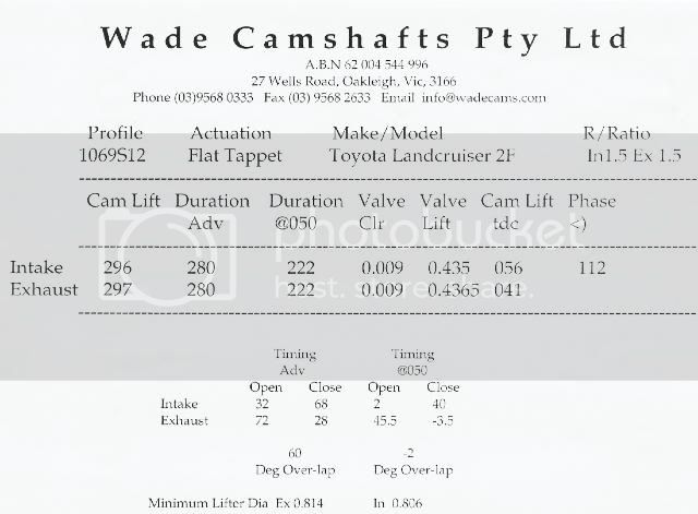
Cam was just delivered :grinpimp:

IMG_5514.jpg

IMG_5515.jpg

IMG_5516.jpg
 
Last edited:
My 2F came back from the machinist today .

I weighed the pistons and the conrods and they weight the same to the exact milligram . ( looks like the balancing was properly done).
I supplied a new clutch assembly and that was balanced as well . ( also included in the balancing : crank , pully , flywheel )

The ARP conrod bolts were machined not to interfere with the camshaft and were included in the balancing process .

Now I just have to wait for the Delta cam that was posted to me from Pennsylvania by a friend - It may take up to two weeks and then there will be a custom clearance process as well :bang:

Interesting read : http://www.scribd.com/doc/6697725/Engine-Dyno-Guide
In the article they say that the longer conrod does not increase low rev torque - That is one of the reasons I chose the 2F over 3F block
 
Interesting read : Engine Dyno Guide
In the article they say that the longer conrod does not increase low rev torque - That is one of the reasons I chose the 2F over 3F block

If that was the case the 3F & 3FE would make torque lower down Toyota's numbers don't support that theory.

IMG-6.jpg
 
A longer conrod doesn't increase the peak torque. They do tend flatten out the torque curve, so off-peak torque can be improved. Years and years ago (back when they published real tech) Circle Track magazine did a back to back comparison of long rods and short rods. They kept everything else the same. The bob-weight, cam/carb/ignition/CR/etc., everything. To do that they had to have some very custom pistons made.

Same day, back to back dyno testing showed that the HP & Torque peaks were too close to declare either a clear winner over the other. the short rod engine was more "peaky", more like a two-stroke than was the long rod engine. The long rod engine was more susceptible to detonation. It was speculated that this was due to the piston's increased near-TDC dwell time.

I have noticed a parallel result in short deck and tall deck 22R's. The short deck (shorter rod) is less susceptible to detonation than was my old tall deck (longer rod) 22R.
 
The longer stroke piston will have higher piston speed - could be why detonation becomes an issue ( rapid rise in cylinder pressure ) . In that study they compare long stroke / small bore vs short stroke / big bore - may not be applicable here as 3F and 2F has the same bore .

I miss the updates of this thread
 
The Circle Track article's test engine had the same bore size. The weight of the piston & rod assemblies were the same, the cam was the same, the compression ratio was the same, heads/rockers/valve springs/etc./etc./etc. were all the same. They noted that each combo did not have an idealized cam, but that they weren't interested in optimizing the cam for each rod length. They wanted to know how rod length affected the performance curves of an identical engine. They tuned each combo (ignition timing and jetting) for best output and that was all. I'd have to try to find that article to confirm, but I dimly recall that the long rod engine combo did not want as much ignition timing as did the short rod engine.
 
Unfortunately updates won't be coming very quickly now. The engine (and the rest of my "stuff") will be moving to a new home in the country in the next week. While the increased space is a good thing, fixing the place up will be consuming the bulk of my free time for a while, I won't have internet at home.
 
The Circle Track article's test engine had the same bore size. The weight of the piston & rod assemblies were the same, the cam was the same, the compression ratio was the same, heads/rockers/valve springs/etc./etc./etc. were all the same. They noted that each combo did not have an idealized cam, but that they weren't interested in optimizing the cam for each rod length. They wanted to know how rod length affected the performance curves of an identical engine. They tuned each combo (ignition timing and jetting) for best output and that was all. I'd have to try to find that article to confirm, but I dimly recall that the long rod engine combo did not want as much ignition timing as did the short rod engine.

If that is the case, you have discovered the reason it makes more power; later ignition timing and still able to achieve maximum cylinder pressure at 15 degrees ATDC. This is the secret to a fast burn head as well. If the flame can be lit later while still getting the max pressure at 15 degrees ATDC, resistance on the compression stroke is decreased and that puts more power to the ground. There must be some term for this, but it is one of the reasons that a Vortec head makes more power that previous Chevy heads. Not only does it flow extremely well, but it requires less ignition advance due to the fact that the turbulence created by the chamber's shape, causes more rapid burning of the mixture. If a longer rod can create the same effect, there will be some gain, although as you mentioned, there is more possibility of detonation with the long rod setup that is not as prevalent with a fast burn head.
 
I would suspect that any reduction in timing needs was more due to the longer piston dwell near TDC and not some much a fast burn situation. This test was done well before the Vortec heads came out.
 
My cam has also arrived in South Africa ( all the way from Tacoma ) .

I took a Melling MC803 ( new) cam and had it ground by Delta

img_4858.jpg


img_4859.jpg


I am very pleased and eager to find out the difference in powercure compared to the 262 cam .

( Adjusting the valve clearance :
Do I use the valve Lash values as in first pic - at TDC ? )
 
Last edited:
My cam has also arrived in South Africa ( all the way from Tacoma ) .

I took a Melling MC803 ( new) cam and had it ground by Delta

img_4858.jpg


I am very pleased and eager to find out the difference in powercure compared to the 262 cam .

( Adjusting the valve clearance :
Do I use the valve Lash values as in first pic - at TDC ? )

Just for comparison here are mine.


IMG-19.jpg
 
My cam has also arrived in South Africa ( all the way from Tacoma ) .

I took a Melling MC803 ( new) cam and had it ground by Delta

img_4858.jpg


( Adjusting the valve clearance :
Do I use the valve Lash values as in first pic - at TDC ? )
Yes, start by installing the cam straight up, and adjusting lash to the cam grinder specs.
Later on the lash & cam timing can be messed with if it seems necessary.
 
Well, I finally got around to touching up the AFM a bit. I didn't end up using any aluminum putty or such, just cut metal. I did three things basically, smoothed out any raised seams in the casting, rounded off the sharp lip where the ends of the casting meet the screwed-on floor of the meter, and smoothed out the transition from the squared meter profile to the round intake tube profile. I should point out that I did not touch the vane or the housing immediately around the vane's travel path to avoid having any effect on the meter's function.

Seam smoothed out on the inlet side of the meter.
IMG_6181.jpg


Rounding off the lip where the meter body meets the floor at the outlet end, before and after.
IMG_4166.jpg

IMG_6187.jpg


Smoothing the transition from the square meter profile to the round intake tube profile, before and after.
IMG_4156.jpg

IMG_6185.jpg


The engine is pretty much ready to swap in. Hopefully I get around to it in the next week or two....
 

Users who are viewing this thread

Back
Top Bottom