HD front recovery points (1 Viewer)

This site may earn a commission from merchant affiliate
links, including eBay, Amazon, Skimlinks, and others.

bjowett

Supporting Vendor
Joined
Oct 28, 2002
Threads
295
Messages
4,367
Location
North Adams, Massachusetts
Toyota supplies good recovery points on their vehicles, and the 200 is no exception. However, when it comes to certain things, like recovery equipment, bigger and stronger = safer. The Tundra has hooks up front that, IMO, are worth upgrading to. The main hook hoop is manufactured from 1" bar stock, up from .71" on the Cruiser, and the tie down loop is welded in place which provides some cross brace structure. The only down side to these is that they hang about 1" lower. The picture below tells the story. Part number is 51960-0C011, unfortunately, purchase price from Toyota is over $200 for a pair at a good discount. Salavge yards might have them cheap. If you want some delivered, I have several sets of new take off units in stock for $75 a pair + shipping.

bighooks.jpg
 
Last edited:
I pulled the trigger on these. Huge difference. Here are a few pics after my first coat of safety red on the new recovery points. I had already drug on the old ones a few times so I hope the 1 inch is not too much lower. They definitely are not going to bend. Thanks Brian.
ImageUploadedByIH8MUD Forum1439052460.075946.jpg
ImageUploadedByIH8MUD Forum1439052472.867757.jpg
ImageUploadedByIH8MUD Forum1439052485.754275.jpg
 
Those Tundra hooks are the beef!
 
I bought mine from Brian (thanks again!), had them powder coated:

LC200TundraHooks_15JUN15_zps6geu6w7r.jpg


And they look great:

LC200NewHooks_15JUN15_zpsskiw9qrn.jpg


HTH
 
I hope not. The website shows sold out yet more appear on your Allstate rigs???! Trick or treat
 
He responded via PM saying he had 1 more, fingers crossed.


CRAP, sold out!
 
Last edited:
Allstate??? I meant your rigs. Autocorrect
 
First time poster and waiting for the 2016 LC release so I can jump back into a cruiser again. I certainly do not want to diminish the contributions bjowett makes towards providing options and input to members, but it is my opinion the LC bracket is stronger than the Tundra bracket in the load cases most likely to fail (sheer and pullout).

If you look at the combined thickness of the material under the bolts, it seems to be over twice as thick. Sheer stress is the force applied divided by the cross sectional area of the combined material perpendicular to the direction of the force. The sheer stress on the LC bracket will be less than half of the Tundra bracket and therefore twice as strong.

Compare that to the tensile stress of the large U member. Similar equations apply where the tensile stress is the force divided by the total area of the material. The LC bracket has a little over half the area as the Tundra bracket (.71" diameter versus 1" diameter). The Tundra bracket is strong in tension.

I won't bore you with the other reasons why the LC bracket is better (LC has shorter legs on the member that looks looks like a bowl, LC has a L section attached to the bowl with weld and fasteners as opposed to welding a U section to it). As a former aeronautical stress engineer though, I would prefer the LC bracket especially if it was powder coated red. :)
 
Hello David. Thanks for your constructive criticism, I do appreciate it. You are going to become a very welcome addition around here.

You bring up a good point, and here are my thoughts on this...

The material under the bolts is the same thickness on both units. The L is not welded into the unit, but is held on by the bolts. It does help with shear load and pull over at the bolted joint of the recovery hoop, though I am less concerned about this area for a catastrophic failure... I would rather see this area of structure start to bend and show the signs of fatigue. Why? We want it to degrade first, before the frame underneath, which we can't replace, or so easily inspect. A good solution here, if we find it to be a problem, is an additional bracket secured here with the same two bolts. Then run back and bolted to the frame in an additional spot, this would place us in double shear and considerably reduce the stresses at these points.

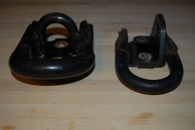
One of the main concerns here is the tensile of the actual loop, and this is where the upgrade lies.. It sees lots of abuse from two sources... connecting hooks, chains, or what one has, to it for recovery, along with rubbing and grinding on the ground. These wear on the bar and create significant stress raisers at the most critical and uncontrolled connection point used during recovery. Working diameter may be slowly decreased as it wears. Toyota has given this point lots of extra room on the Tundra unit. Additionally, the larger bar gives our nylon recovery straps a larger radius to wrap (keep them isolated from those scratches and wear marks!), which keeps them further away from their minimum bend radius, and thus performing properly.

We can discuss this further if you, or anyone else wants. As there are other areas, the legs, the width, etc that all factor into what we are using them for. I'm always game... and again, welcome!
 
I'm interested in this discussion, but underqualified to add anything worthy. :popcorn:
 
I would not want to run a strap though that hole. Fatigue life could be increased by rounding those corners. Given the material and thickness, it will be very tough to break

When it comes down to it, we should really place those bolts in double shear, dowel pin the base to the frame, and run an additional bracket rearward.

ARB recommends putting a shackle on backwards on the recovery point. So the round part is on the recovery point & the strap is on the pin. I don't know if this is good/bad/acceptable or not. The main issue would be people actually remembering to do it.

I think the stipulations on these recovery hooks are:

1. Fail before other more serious damage occurs (but don't fail unnecessarily)
2. Fail such that no one gets hurt
3. Fail such that no damage other than the recovery point itself occurs.

Simple enough conditions, eh!? :)
 
The strap is not run through the slot/hole in the ARB recovery point.

The ARB recovery point has a slot to allow the bow of the shackle to be fed through and the strap attached via the pin instead of the bow.

The ARB recovery point for the Toyota Land Cruiser 200 Series is designed to be fitted to the left or right hand side of the chassis or both.

I am considering ARB front recovery points fitted on both sides of the chassis which would allow the use of a recovery bridle between the two ARB recovery points. Thoughts?
 
Any thoughts on the ARB Front Recovery Point (Part no. 2815010) designed specifically for the 200 Series Land Cruiser (8000kg Snatch Strap Rating, Bow Shackle Rating 4.75t)?


200SeriesRecoveryPoint-538x303.jpg


    • Recovery eye manufactured from 350 grade 20mm plate
    • Finished in a hard-wearing red powder coat
http://www.arb.com.au/toyota-landcruiser-200-series-2012-present/recovery-points/
Hmmmm. Will check into those.

Anyone rig a rear recovery point after ARB install? I've used my hitch with pin with a Clovis and it worked. Hitch is in frame off course. I guess I could drill and tap frame but too far back?
ImageUploadedByIH8MUD Forum1439326842.762059.jpg
 
@bjowett: I completely agree with you that thickness adds durability. If the existing hardware is experiencing significant damage from use, the fitting should be replaced. The individual operating the winch is ultimately responsible for determining if the attach points are sufficient and undamaged. I still stand by my belief thought that the LC bracket is stronger in the load cases most likely to fail.

Assuming the material properties are the same (big assumption) and the welds do not have contaminants, the pullout loads and shear stresses on the hat section bracket are the most likely failures due to the overturning moment created when the line of force is not parallel to the large U fitting.

In addition, the welds of the Tundra fitting of the smaller U fitting used when strapping the LC to a trailer seem vulnerable if struck by a rock . The LC bracket is not welded, but instead held by bolts and therefore inherently stronger. If there is damage to the welds on the smaller U fitting, this in turn could further reduce the structural integrity of the hat section during a recovery.

As simple as the fitting looks, there are some complex use cases involved. The only way to know for certain is to listen to the guidance of an experience stress engineer (not me by the way) or to model the two (2) fittings using a non-liner finite element analysis tool. I sell those solutions for a living, and I can tell you Toyota is among the most advanced companies in the world in terms of their simulation and optimization capabilities.

This is a great discussion, and I certainly appreciate sharing the different perspectives. Thank you for the welcome to the forum. :)

@elkeye: I agree with bjowett.
 
After thinking more about this, I'm going another route. (Edit: sold these to another mud member)
 
Last edited:

Users who are viewing this thread

Back
Top Bottom