Builds Finally got my own...Meet BeBe

This site may earn a commission from merchant affiliate
links, including eBay, Amazon, Skimlinks, and others.

OK. What color are those wires and what do you think they go to? It looks like two of them (the Light Blue ones with White and Green) are factory wires and then there are two white ones...probably not factory....

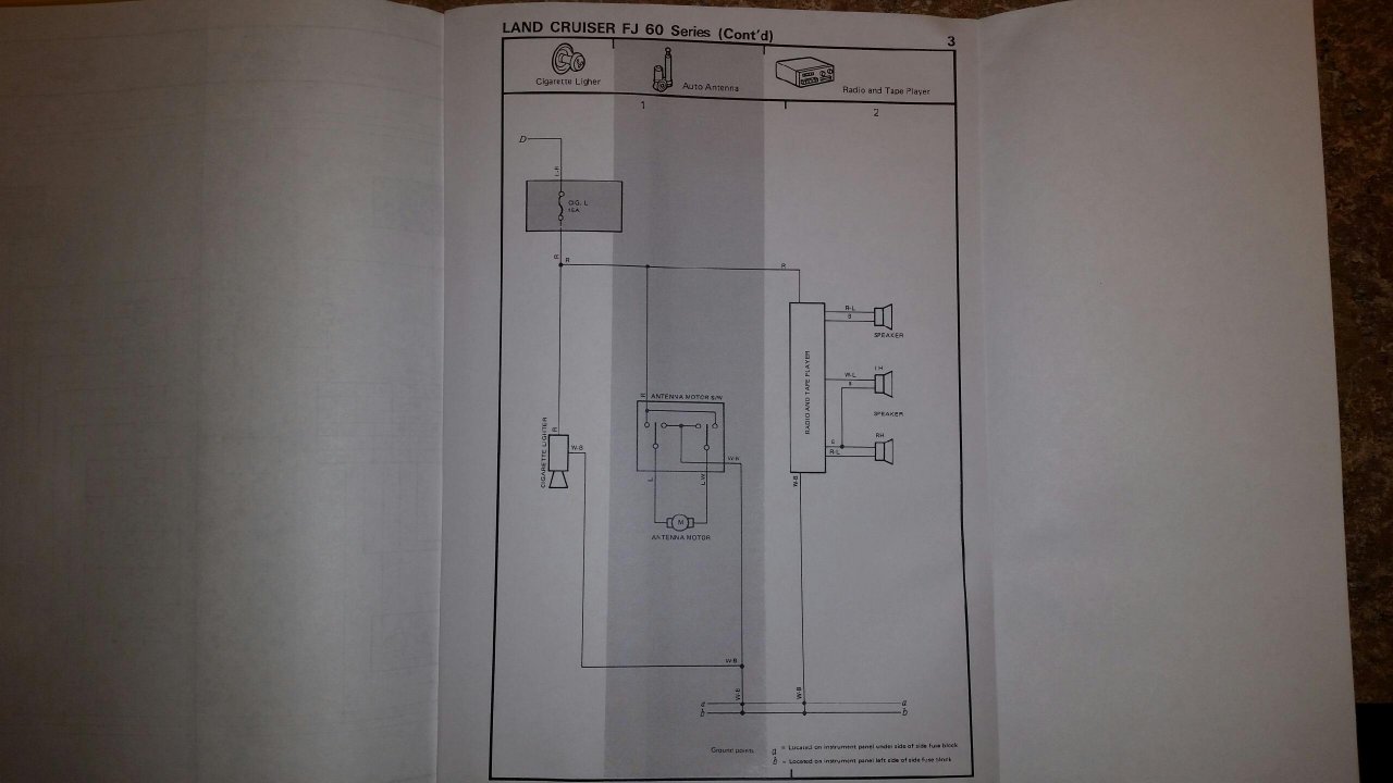
Looking at the wiring diagram from the 4/95 Supplement, and trying to match color pairs to wires in the diagram associated with the radio:

Light Blue with White stripe (LW) wire - Antenna motor
White with Light Blue stripe (WL) wire - LH speaker???

Light Blue with Green stripe (LG) - ??
Green with Light Blue stripe (GL) - ???
Green (G) - RH speaker??


img_0036-jpg.969796
 
Ok so if I remember correctly the green with blue strip goes to what was the old cruise control connector. Since I didnt know what it was at the time I did not cut the wire. The white wire I am not sure about I will have to look again tonight.
 
Ok so if I remember correctly the green with blue strip ....
Hmm..is it Green with Blue stripe (GL)...or Blue with Green stripe (LG)?
...and is it a factory wire?
If so, then it should be able to be identified on the wiring diagram (you'll notice, if you already haven't noticed, that the lines on the diagram are labeled by their color code...and a heads up, sometimes you'll see RH and LH which stands for Right Hand and Left Hand...speakers, for instance).

I guess determining and confirming which one of those is a factory wire, what circuit it is supposed to be on (wiring diagram) and if it is still being used for that original factory purpose is a good place to start.

And for the two white wires (I see two in the picture, but only one looks like it is tapped into that blue gizmo), they are most likely installed by the PO. Maybe trace or test to see what circuit they are on?

Also, did you say there was a car alarm installed on this vehicle? And are car alarms usually wired up with the radio?
 
Is this what that blue gizmo is?

If so, what is it's function (how is it supposed to work...for instance, is it supposed to splice two wires into a third wire??) and in your picture above, which wires are going where into this thing?

upload_2014-12-18_11-47-2.webp
 
That is something like that little splice connector. The way it is different though is that it has a spade connector on the side that the power wire from the stereo plugs into. The problem results from the spade pushing the splice connector around which causes other shorts.

Here is what it looks like..
tapped.jpg


What I haven't linked is the sudden overvolting that I mentioned. where suddenly I would have my meter go up to the top line just below 16v, which I will call 14.5v and stay there for a bit. That is completely new and something that I have not been able to replicate.
OK. So on your vehicle:

What is the color wire that that gizmo splices into (ie the red wire in this example picture you posted)...
...and what is the color wire that is spliced off that gizmo (the green wire in this example picture you posted)?
 
Ok spliced off the gizmo is a red wire that then leads to a yellow wire that I traced all the way back to the stereo power.
I will have to take a look tonight when I am off work to see what color it is splicing into on the connector.
 
Ok spliced off the gizmo is a red wire that then leads to a yellow wire that I traced all the way back to the stereo power.
OK. I'll bet that the yellow wire is the aftermarket radio power wire (comes directly off the radio and came with the radio - soldered into the radio). And if you look at the wiring diagram image above, you will notice that the factory R (Red) wire is the 'hot' (12V+ power) switched wire between the CIG/RADIO fuse and the Cigarette Lighter and Radio. It looks like there might be a factory splice (RED spliced to/from RED) there so that both the Cigarette Lighter and Radio both share the same factory R (Red) wire off that side of that CIG/RADIO fuse.

EDIT: I just noticed that the 'Antennae Motor' also runs off a R (Red) wire, so you might find a splice for that one as well....

I will have to take a look tonight when I am off work to see what color it is splicing into on the connector.
Yeah, do that. If you find that it is spliced from another R (Red) wire, then trace that one and see if it leads from the fuse box to the Cigarette Lighter...if so, then it makes sense and it would seem that the OP spliced the yellow radio power wire into the factory switched Radio R (Red) wire...which is the correct thing to do...

Also, if you look at the wiring diagram, you will notice that on the other side of the CIG/RADIO fuse, there is a wire (I think it is labeled LR which would be factory Light Blue with Red stripe) that runs route 'D' back to the ACC pin at the Ignition Switch.
Notice that the the CIG/RADIO circuit is the ONLY circuit on route 'D'.
That means that if your wiring is good between the Ignition Switch, through the CIG/RADIO fuse and to each of the CIG and RADIO components and their grounds, then the problem would lie in the Ignition Switch or on the other side (battery side) of the Ignition Switch...
 
Last edited:
Ok splice with spade looks to be attached to a Green with Blue/Light Blue strip wire... From there the PO has a small section of red that leads to a section of yellow that leads to the radio (so red and yellow are PO installed and not part of original harness). I will confirm colors tonight when I get a chance and can get a good look (maybe better pic) of the section/master connector.

Ultimately, I have a light upgrade harness (one of SLCFJ62s, the ultimate one) with the included auxiliary box so I had planned on hooking the stereo up to that eventually when I built a bracket to install it. Looks like I will be doing a little welding this weekend to build a bracket to install that and the direct ALT to Battery connector I had @Fourrunner build for me along with his battery cable kit.
 
Ok splice with spade looks to be attached to a Green with Blue/Light Blue strip wire... From there the PO has a small section of red that leads to a section of yellow that leads to the radio (so red and yellow are PO installed and not part of original harness). I will confirm colors tonight when I get a chance and can get a good look (maybe better pic) of the section/master connector.
OK, then it sounds like PO used some of his own red wire as an extension on the radio's yellow power wire to tap into what he thought was a 'good switched' 12V+ power source on the factory harness...if indeed you can confirm that this Green with Blue/Light Blue stripe is factory harness wire...

...and looking at the wiring diagram, I'm trying to find a GL (Green with Light Blue stripe) wire to see what circuit he would have tapped into. But the resolution on the images of this wiring diagram suck. Do you have a hardcopy or know of another place to download a softcopy of this Supplement from?

Can you read if the wire coming off the bottom right of the Ignition Main Relay is labeled GL???...or is it labeled BL? You might be able to check on the vehicle to see if there is a GL wire leading to/from the Ignition Main Relay...

upload_2014-12-18_15-43-27.webp


Looks like 'Turn Signal Flasher' has a GL wire:

And 'Stop Light Switch' has a GL wire:
 
Last edited:
Ok so I just went out and looked....
The PO spliced into an existing harness that is a two wire harness that comes off a main harness that is behind the gauges on the steering column.
The two wires that are spliced into are a Green Wire with White Strip (which you can see is spliced into a white wire section) and a Green Wire with Blue strip (we will call it GB)..

The GB has the splice indicated above with a spade connector that powers the radio.
 
...and a Green Wire with Blue strip (we will call it GB)..
Actually, according to the Toyota color code, Blue is 'L' and Black is 'B', so we probably should stick to Toyota convention for the sake of clarity, if not for us, for future MUD users who might read up on this...

From the 1980 Chassis_Body FSM:

Wiring Color Code Body Electrical_page 13-2 in 1980-chassis-body FSM.webp


From the 1980 Chassis_Body FSM:

Wiring Color Code_page BE-2 in 1984-chassis-body FMS.webp


...not sure if the 4/85 supplement has any additional changes...
 
Ok so I just went out and looked....
The PO spliced into an existing harness that is a two wire harness that comes off a main harness that is behind the gauges on the steering column.
The two wires that are spliced into are:
a Green Wire with White Strip (which you can see is spliced into a white wire section) and...
a Green Wire with Blue strip has the splice indicated above with a spade connector that powers the radio.

Green with White stripe (GW) -
In the picture you posted in post #539 I see two White wires (or is it the same wire?). Which one is the one 'spliced into' the GW, how is it spliced in and where does the White wire lead to?
If there are two White wires, then what and how is the second White wire 'spliced into' and where does that White wire lead?

Green Wire with Blue stripe (GL) -
Above in post#550 I found what I think to be 3 circuits in the factory harness that have GL wires...so if the PO spliced into one of these, then the trick now is to confirm which circuit he spliced into and see if that explains the symptoms you are seeing.


Also, if you pull the radio or are poking around behind the radio, see if you can identify the factory 'hot' Red (R) and ground (BW) wires for the radio...and see if the factory 'hot' Red (R) is still getting power...
...and if he didn't use the factory ground, you'll have to see how/where he grounded the radio...
 
Green with White stripe (GW) -
In the picture you posted in post #539 I see two White wires (or is it the same wire?). Which one is the one 'spliced into' the GW, how is it spliced in and where does the White wire lead to?
If there are two White wires, then what and how is the second White wire 'spliced into' and where does that White wire lead?.

It is actually one wire, it just goes out of the picture. Must have been broken off at some point with how short the section is OR the person that installed the cruise control cut the wrong wire and then realized it later.

Green Wire with Blue stripe (GL) -
Above in post#550 I found what I think to be 3 circuits in the factory harness that have GL wires...so if the PO spliced into one of these, then the trick now is to confirm which circuit he spliced into and see if that explains the symptoms you are seeing.
I will have to pull the gauges to see what I can find in there. Should be off a little early tomorrow so hopefully will have more light to work with.

Also, if you pull the radio or are poking around behind the radio, see if you can identify the factory 'hot' Red (R) and ground (BW) wires for the radio...and see if the factory 'hot' Red (R) is still getting power...
...and if he didn't use the factory ground, you'll have to see how/where he grounded the radio...

If I remember correctly the ground is the original ground from the factory but the HOT was not one that I could find and when my buddy and I installed the stereo we just went off what was there. With that being said, I would still like to plug into my new upgraded light harness when I install that, which means I will be running a dedicated ground and hot to the auxiliary box.

The other thing I will have to find is a light to tap into for the illumination feature of the stereo. This allows for a NIGHT and DAY setting that automatically dims the lights when either A.) the lights are turned on, or B.) a specific time is hit (which I havent gotten to work).
 
I THINK (hard to read) that the Ignition Relay has a GL wire:

upload_2014-12-18_21-21-30.webp


The Turn Signal Flasher has both a GL and GW wire:

upload_2014-12-18_21-16-42.webp


The Stop Lights have both a GL and GW wire:

upload_2014-12-18_21-17-33.webp
 
With the way the Radio is currently wired, under what condition(s) will the Radio power on:
1) Key is out of ignition
2) Key is in ignition and ignition switch is turned to ACC
3) Engine is running
 
Ok just went and confirmed that the large blue connector that is seen in the picture goes to the brake pedal switch. So these are the brake/tail light wires that you indicated in your post!!!!

Functionality of the radio is when the key is in the ignition and turned to ACC.
 
I need to know what this says:

upload_2014-12-18_21-34-50.webp


it's from here:

upload_2014-12-18_21-35-27.webp


...which is from here:

upload_2014-12-18_21-36-55.webp


upload_2014-12-18_21-36-3.webp
 

Users who are viewing this thread

Back
Top Bottom