.... your primary glow controller ...
Did you mean the Main Glow Plug Relay [or no1. Glow Plug Relay as some say]? Or do you mean something else?
Okay... I have checked some things:
1- Pre Heater Timer
Did not check, because I don't know what to check as to the 9 connection system I have and I have not encountered a schematic drawing.
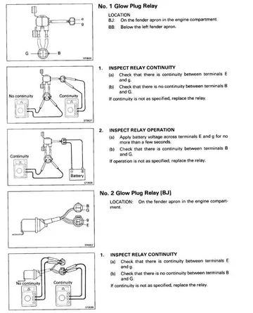
2- No.1 Glow Plug Relay continuity and operation
Is working like it should; no continuity on the relay, continuity on the plugs terminals leading towards the relay and continuity on the relay when applied 24 volt to the terminals leading towards the relay.
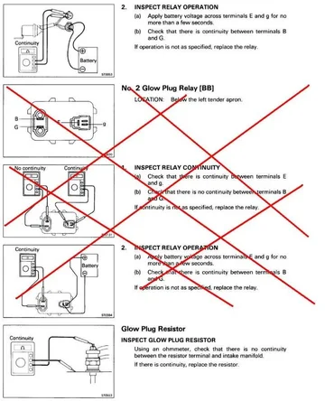
3- No.2 Glow Plug Relay continuity and operation
Is working like it should; no continuity on the relay, continuity on the plugs terminals leading towards the relay and continuity on the relay when applied 24 volt to the terminals leading towards the relay.
4- Glow Plug Current Sensor continuity
Is working like it should, continuity between the sensor terminals
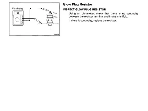
5- Glow Plug Resistor continuity
Is working like it should, continuity between the resistor terminals
6- Water temperatur sensor
Is working like it should, reading an 1.8 Ω which resembles roughly the outside temperature of 30˚ here in Salvador as the engine is cold.
So I am curious how to test the Pre-Heater timer with 9 connections.
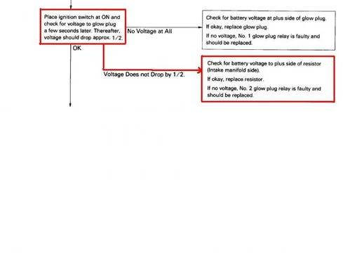
And another strange thing I discovered when testing the No.1 Glow Plug Relay. I applied 24 volt to test the relay. It closed and I could measure continuity. But then I measured the voltage on the bus bar and I saw a shocking result on the readout display of the multimeter: 24 volt! Shouldn't it be less? In order to work with the 14 volt glowplugs? Who regulates the voltage in a Super Glow System?
Adventurous greetings,
Coen
...... as I await some 14 volt plugs. And I will only fit those if I have checked if something is fault of making those plugs explode or if it was just a faulty plug?...


