4BD1T into FJ60 Fit Issues

This site may earn a commission from merchant affiliate
links, including eBay, Amazon, Skimlinks, and others.

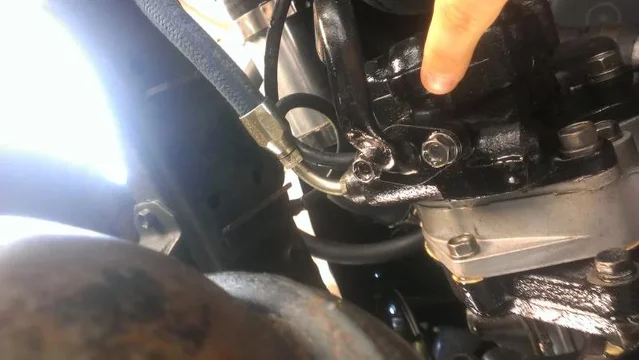
I thought the 4BD1 and 2 had the same PS pump set up? Looking at my swap, I don't see how the line could hit the diff.?

I know your adapter positions the engine further rearward by maybe an inch, but I have many inches of clearance on mine, both vertically and horizontally, and I imagined yours to be the same.

Is it the return or supply that hits?

Here is what mine looks like. Maybe you can reroute the hose/fittings?

Doug

IMG_5227.webp


IMG_5228.webp


IMG_5223.webp
 
Glad the beads on the pipe worked, they always helped on the cars I use to build. That's crazy that the PS feed line got crushed, I would be worried about hitting it to hard that something else breaks (timing case, pump ect). Getting some hard urethane bump stops would be a good idea to start to get you by till you sort out more lift. I have looked at that line a few times on mine and I can not see any way to move it or make it any tighter to the pump.

Your adapter must position that engine much further back than others have.
 
I just looked at my set up, as Jeremy said, it will take some work to come up with a shorter 90. I see a few options, it looks like the pipe could be cut off the flange, shortened and re-welded/brazed back on. This would give you maybe an inch more clearance.

On mine, the steel pipe exits the pump and runs forward then turns to the rear and upward just above the diff. What part of the pipe did the diff contact? Maybe if you made a new pipe/hose than ran forward and to the side it would clear? Or you could make a low profile billet piece to bolt to the pump fairly easily too?

Post a few pics when you can. There's always a way!

Doug
 
I am not going spring over axle. :flipoff2:

It is the suction pipe coming out of the bottom. It contacts at the first bend where it goes horizontal.

IMAG0325.webp

There is currently about four fingers of space between the differential and the pipe. And about 5 or 6 between the passenger side bump stop and the axle.

IMAG0326.webp
IMAG0327.webp

I currently have a few options as I see it:
1) saginaw or equivalent belt driven pump. ---- I would prefer to not do this one.
2) Notch the differential ----- lots of time and to do this. May not work since the ring gear is near the place that needs to be notched
3) Spring over axle. ---- No
4) Extend bump stops ---- Not a permanent fix. Not a good plan moving forward.
5) Rotate the power steering pump and make sure that two of the bolts still attach. ---- This isnt too bad of an idea.
6) Someone mentioned this above. Machine a part that is lower provide....maybe out of bar stock? Would be a significant machine endeavor.

I am going to pursue 5) to begin with and then reevaluate.

IMAG0325.webp


IMAG0326.webp


IMAG0327.webp
 
Well looking at your pictures I do not see why extending the bump stops is not a good idea? I mean as it sits now the engine is your bump stop so extending the "real" bump stops does not lose you anything. If you did that and machined a lower profile pump fitting I think you would be ok.

I cant see turning the pump and retaining any more than one bolt the way they are spaced.

The ultimate fix is more lift and keeping the lower bump stops to regain travel lost with just lower bump stops.
 
Seeing the pictures, it looks like limiting the travel or more lift is going to be needed, no matter the solution to alter the PS connection.

Rotating the pump is a poor solution. The PS pump drive gear acts as an idler for the IP and you don't want that not to be perfect. Plus the engineers put 4 bolts on the pump for a reason.

As far as I know, no one else using these engines in a 60 has had this issue. I wonder if your engine mounts are lower, besides having the engine sitting an inch or so to the rear?

Doug
 
I just checked my spare 4BD2 engine to see if you could rotate the PS pump...NO!

First, there are only 3 bolts with odd spacing on a triangular pattern on the mounting face.

Second, the pump will not fit into the timing cover in any position other than stock. Any position than stock, and you would have to remove a timing cover bolt also.

Third, rotated 180, the suction pipe flange hits the timing cover protrusion for the IP drive gear. The inlet is part of the pump body also.

Sorry for the news, but it was easy for me to check this for you. Here is a picture of the timing cover at the PS pump area for reference.

Doug

P1080136.webp
 
Doug, thanks for using your spare! That is a huge help!

I was trying to figure out if I am sitting lower than everyone else. I guess its possible, but there isnt much clearance to the hood as it is.

The truck is already pretty high, so putting more lift isnt and idea that thrills me. Hmm...I wonder about raising the engine. Or lowering the bump stops.
 
Lowering bumpstops is not a big deal, should flex it up and check clearances after installing a lift anyway. This is simple and a viable solution for your current problem.
How much lift are you running?
 
I went down to LA yesterday and saw Doug. After looking at his truck and mine, we agreed that my engine sits an inch or maybe a bit more lower than his and also two or so inches back.

I am going to look at adding spacers to the engine mounts to raise the engine and also spacers to the bump stops to lower them a bit. I will need to check all of the connections to the engine when I do it. Ones that I know will be tight are the exhaust pipe, intercooler pipes, heater hoses at the firewall, and one or two other places.

I have an old man emu heavy+ lift....not sure how many inches that makes it.

The drive to, around, and back from LA was the longest I have done and I put about 250miles on the truck. It went pretty smooth except my engine temperature went though the roof at one point. I found that the 30A fuse on the fan controller for the Ford Contour fans blew. It was in the middle of the day and it was hot, so the fans must have been working hard. But I need to figure out why it blew.

I also now need to replace the thermostat I suppose.

I also found water/fluid in the passenger footwell. In writing this post, I think I just realised that it may be a coolant leak from the heater hoses at the firewall. EDIT: I went and vacuumed up the coolant (which it was). It is either coming from the heater or from the heater hoses at the firewall, not sure yet. I am thinking the hoses as the heater worked before (but I could have damaged/loosened the hoses on the heater) and because you can see some (not a lot) of coolant running down the engine side of the firewall. I couldnt see where in the passenger compartment the coolant was coming from without taking apart more stuff.
 
Last edited:
Alright, so I am working on raising the engine and I am running into a couple roadblocks, mainly the firewall. I am aiming to raise the engine an inch.

The wastegate actuator on the turbo is contacting the firewall when I raise the engine even a little (1/4 inch). A picture with the engine NOT raised is below. The other contact issue is the turbo intake and the firewall/firewall lip. I am trying to think of a way around that too.

For the actuator, I am pretty positive that it needs to be relocated. Or I need to notch out the firewall (keep in mine that I really such at welding sheet metal. This is a pretty difficult thing here, so I am considering taking it too someone, but I wanted to get your guys' opinions and thoughts first. Where would you relocate it too. How do you relocate an actuator and keep the arm length correct? What other things do I need to consider?

A few pictures (they are going to span two posts):
With turbo intake attached
DSCN0430[1].webp

Another with turbo intake attached:
DSCN0431[1].webp

Close up of actuator:
DSCN0438[1].webp

DSCN0430[1].webp


DSCN0431[1].webp


DSCN0438[1].webp
 
More pictures:

Zoom out of actuator
DSCN0439[1].webp

And the area where the firewall was cut away to make room for the turbo intake
DSCN0440[1].webp

DSCN0439[1].webp


DSCN0440[1].webp
 
So my mind is thinking.....does anyone know what is behind this on the firewall? Could I bump the firewall into the passenger cabin maybe a solid 2 inches? What would it hit?
 
So my mind is thinking.....does anyone know what is behind this on the firewall? Could I bump the firewall into the passenger cabin maybe a solid 2 inches? What would it hit?

Hi Mitch,
I had my dash off when I was restoring it last year and I think that area is pretty open. I think there is just the flex tube that takes air to the vent on the left side of the steering wheel.

Don
 
Well a few thoughts, it looks like the turbo to intercooler pipe is already rubbing on your hood. So may make it worse if you lift it. Second is it looks super tight back there already, that intake adapter cant be helping that turbo breath.

Why not look at killing both with one stone and flip the turbo to point the intake forward? yes you will need to rework the down pipe and lines possibly but it would git you a lot more room at the fire wall, allow a better slowing intake and also allow you to move the intercooler pipe down and away from the hood. This would give you the room you need with out hacking up the firewall any more.

Just my .02c

Rotating the turbo won't work.

The turbo currently "curls" into the engine, if I flip it, it will curl out and then into the brake booster.

Also with how the compressor output works/points, I would have less vertical space the more I move the output to the front of the truck.

As for the intake, that part isn't the best thing, but the cross sectional volume of air of the rectangle (about 4" x 1.5" = 6inch squared) at its slimmest point is almost the same as the circle (7 inch squared).

I will go take a look at rotating the turbo, but I am pretty sure these reasons, especially the first one, is why I didn't do this to start with. The brake booster makes things very tight.

Another option would be to out the turbo vertically, but then the cooling oil wouldn't not flow correctly.

Well I am not in front of the truck but if you spin it so the inlet faces the front of the engine the turbine will curl down and away from the engine possibly giving you more room to work with. Also that break booster is massive! I could have sworn the later FJ60's has much shorter boosters? Maybe worth looking into then you can remove the spacer you are running on it now and have up tight against the firewall. Turning your what looks like 8-10" long booster into a 4-5" long booster.

The output of the compressor can be clocked to what ever position you wish although after seeing the result of the last attempt it may not be wise. If you flip the turbo to front facing you would need to clock both the compressor and the turbine.

I understand how the inlet to the turbo is suppose to work in that setup. I just question how much of a restriction the changes in shape and direction are causing to the flow. Its got to be introducing a lot of turbulence to the incoming air thus reducing flow. :meh:

I guess it really comes down to how much you are willing to change to make it work he way you want it too. As with any swap you need to be fluid with your design and adapt in the way "you" feel is best.

:cheers:
 

Users who are viewing this thread

Back
Top Bottom