
Navigation
Install the app
How to install the app on iOS
Follow along with the video below to see how to install our site as a web app on your home screen.
Note: This feature may not be available in some browsers.
More options
Style variation
You are using an out of date browser. It may not display this or other websites correctly.
You should upgrade or use an alternative browser.
You should upgrade or use an alternative browser.
Build 1HNDRD build
- Thread starter skyblue
- Start date
Member Builds and Stories
This site may earn a commission from merchant affiliate
links, including eBay, Amazon, Skimlinks, and others.
skyblue
SILVER Star
- Thread starter
- #103
Installed the rear lights this evening. Connected and operational!
(still need to connect to switch thru relay/fuse... Also I want to tidy up the connection points at the corners of the rack)


!!!
I stuffed the wire/loom into the crossbar channel and used a piece of double-sided tape every 8" or so... We'll see if it works long term...

Side lights next.. Or maybe hook up the light bar.
Or maybe something else
(still need to connect to switch thru relay/fuse... Also I want to tidy up the connection points at the corners of the rack)
!!!
I stuffed the wire/loom into the crossbar channel and used a piece of double-sided tape every 8" or so... We'll see if it works long term...
Side lights next.. Or maybe hook up the light bar.
Or maybe something else
Looks awesome! Cant wait to see it here in Colorado! 
skyblue
SILVER Star
- Thread starter
- #105
Good progress the last couple of evenings...
Finished mounting/connecting the rack lights and then realized that one of the will interfere with the awning so I'll need to slightly relocate it once I mount the awning... I still need to tidy up the wires and secure them to the rack. I ordered a few clamps and fasteners for it. Below are a couple of random pictures.


Next I resumed and finished the fuse panel assembly..


Finished mounting/connecting the rack lights and then realized that one of the will interfere with the awning so I'll need to slightly relocate it once I mount the awning... I still need to tidy up the wires and secure them to the rack. I ordered a few clamps and fasteners for it. Below are a couple of random pictures.
Next I resumed and finished the fuse panel assembly..
skyblue
SILVER Star
- Thread starter
- #106
This evening I got the panel installed and quite a few of the connections completed..

The 120A breaker is probably redundant but I figure it can double as a master switch for aux battery output
I've got 6 relays for the lights, 1 for future air compressor, 2 for future Locker actuators, and 1 spare circuit in case I have another idea. The last relay on the line is for the winch master switch which will run directly off the main battery.
I also have 2 spare non-switched positions on the fuse block one of which will be the circuit for power to the rooftop tent. (light, phone charger, etc)

The National Luna 100A in line fused connection (without a fuse for now)

Also finally received the AGM battery that I ordered a month ago and secured it into place

Next:
- aux battery connections
- connect switch wires and light wires to terminal strips
- learn how to correctly connect switches
- install switches into overhead console (wire is already in place)
- locate power source for switch backlighting
- run wires from fuse panel to front bumper area for driving lights
- connect winch and winch master switch
- probably forgetting several things
Feels good to see it coming together..!

The 120A breaker is probably redundant but I figure it can double as a master switch for aux battery output
I've got 6 relays for the lights, 1 for future air compressor, 2 for future Locker actuators, and 1 spare circuit in case I have another idea. The last relay on the line is for the winch master switch which will run directly off the main battery.
I also have 2 spare non-switched positions on the fuse block one of which will be the circuit for power to the rooftop tent. (light, phone charger, etc)
The National Luna 100A in line fused connection (without a fuse for now)
Also finally received the AGM battery that I ordered a month ago and secured it into place
Next:
- aux battery connections
- connect switch wires and light wires to terminal strips
- learn how to correctly connect switches
- install switches into overhead console (wire is already in place)
- locate power source for switch backlighting
- run wires from fuse panel to front bumper area for driving lights
- connect winch and winch master switch
- probably forgetting several things
Feels good to see it coming together..!
Jesus, you do fantastic work! Love the build
Impressive layout. On point wiring 
skyblue
SILVER Star
- Thread starter
- #109
A bit more progress today...
I got all the connections made on the panel except for winch master circuit (wires in place, just need to connect) and the future stuff (rock lights, lockers, air compressor)

Late this evening I made the discovery that 3 of the terminals on the strip are cross-connected somehow...
I think it's either in the terminal strip itself (unlikely) or a couple of connectors are stripped & touching underneath the panel. This would be a major time-consuming correction...
I'll need to track it down and get it fixed.
Anyway, prior to that unfortunate discovery, I made all the connections on the dual battery.

Controller is working as it should...

Engine bay overview..

I can see the light at the end of the tunnel...!
I got all the connections made on the panel except for winch master circuit (wires in place, just need to connect) and the future stuff (rock lights, lockers, air compressor)
Late this evening I made the discovery that 3 of the terminals on the strip are cross-connected somehow...
I think it's either in the terminal strip itself (unlikely) or a couple of connectors are stripped & touching underneath the panel. This would be a major time-consuming correction...
I'll need to track it down and get it fixed.
Anyway, prior to that unfortunate discovery, I made all the connections on the dual battery.
Controller is working as it should...
Engine bay overview..
I can see the light at the end of the tunnel...!
skyblue
SILVER Star
- Thread starter
- #110
I also got started on installing the switches...


I'm switching negative per the experts' recommendation. I'm pretty much at a standstill on the switch connections until I can find some answers on how to connect with this configuration. I have 1 common ground, 1 wire for each switch, and 1 wire for dash illumination. I have 5-pin rocker switches. I have not been able to find a wiring diagram for the switches for the negative switching
If anyone sees this and can help, please let me know.
Other questions:
- Where can I tie into the dash illumination?
- And when I do, will this create an unwanted link between the main battery and the aux battery?
- when connecting relays for negative switching, do pins 30 & 86 go to + or pins 30 & 85..?
Thanks in advance
skyblue
SILVER Star
- Thread starter
- #111
The cross-connection I mentioned has mysteriously corrected itself... I tested it every way I could think of and tried to duplicate anything that might have contributed to it yesterday but couldn't make it do it again... So that's weird.

I'm still seeking information on the above questions...
I'm still seeking information on the above questions...
skyblue
SILVER Star
- Thread starter
- #113
So I had to back up and re-do some things...
After spending several hours in systematic trial and error, a couple of conversations with @RocketCityCrzrs, a few you-tubes, and several Google searches, I finally determined that it is not possible to achieve proper switch illumination in a standard rocker switch while switching ground... You can get close, but not correct. (accessory on/off isn't a problem, dash lights illumination can be done... However, the upper switch LED will be either constant or reversed) Because I am adverse to anything incorrect, I decided to change my format and put my switches on the positive side.
A keen eye will notice a difference here versus the earlier pictures.

What I don't like is the fact that black is not ground... That would have simply been an unreasonable amount of rework. I swapped white and black in the relays and connected white to ground... Everything tests out perfect now so I'm back on track.
I hope to wrap up the electrical (phase 1) this week.
Can't wait...
After spending several hours in systematic trial and error, a couple of conversations with @RocketCityCrzrs, a few you-tubes, and several Google searches, I finally determined that it is not possible to achieve proper switch illumination in a standard rocker switch while switching ground... You can get close, but not correct. (accessory on/off isn't a problem, dash lights illumination can be done... However, the upper switch LED will be either constant or reversed) Because I am adverse to anything incorrect, I decided to change my format and put my switches on the positive side.
A keen eye will notice a difference here versus the earlier pictures.
What I don't like is the fact that black is not ground... That would have simply been an unreasonable amount of rework. I swapped white and black in the relays and connected white to ground... Everything tests out perfect now so I'm back on track.
I hope to wrap up the electrical (phase 1) this week.
Can't wait...
skyblue
SILVER Star
- Thread starter
- #114
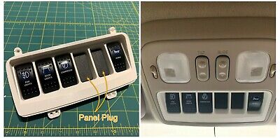
Finally got the main switch panel connected and semi-installed... I tried my hand at soldering with mixed results. There is not enough space for the crimp-style connectors so I had to used solder and keep everything low-profile. (more on that below)


Everything (including switch illumination) works as it should.
However, the sunglasses cubby is not really quite adequate for the size of the switch panel even with the connections being soldered... It's pretty much stuffed and doesn't look awesome. I'm going to need to come up with a solution to make it look cleaner. See picture in next post.
skyblue
SILVER Star
- Thread starter
- #115
I can get it to snap in closer than this but it's not great... Thinking maybe I could carefully bend the switch pins over???
We'll see...
Anyway, it does feel like progress nonetheless. A couple of miscellaneous items to wrap up this weekend and I should be able to finally move on to bumpers..
Finally got the main switch panel connected and semi-installed... I tried my hand at soldering with mixed results. There is not enough space for the crimp-style connectors so I had to used solder and keep everything low-profile. (more on that below)
View attachment 2345044View attachment 2345045View attachment 2345046View attachment 2345047View attachment 2345048
Everything (including switch illumination) works as it should.
However, the sunglasses cubby is not really quite adequate for the size of the switch panel even with the connections being soldered... It's pretty much stuffed and doesn't look awesome. I'm going to need to come up with a solution to make it look cleaner. See picture in next post.
Have you checked out @BenCC 's work? He's doing some crazy cool 3D Printing stuff for the 1HNDRD Series. I think his M4V1.4 might be just the fix for you Sir.
Multiple Rock Switches Mount for Toyota Land Cruiser 100 Series | eBay
Fits Land Cruiser 100 Series with the large opening on the overhead console. I have three versions of the multiple-switch mount.
www.ebay.com
skyblue
SILVER Star