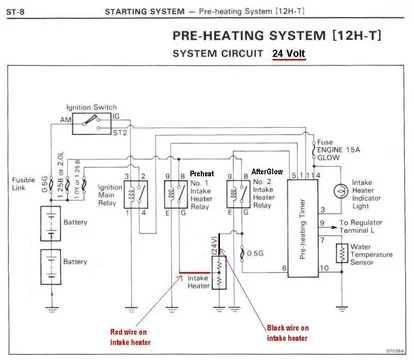
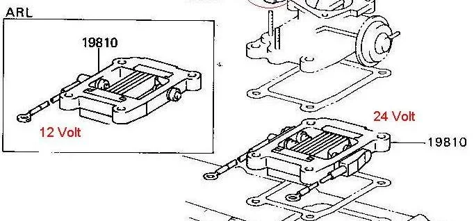
I don't think they are being reduced to 12v for each screen.
They are both running at 24v.
The 12v heater uses a single screen and it is also a smaller screen.
This is how i imagined it works...
Follow along with the video below to see how to install our site as a web app on your home screen.
Note: This feature may not be available in some browsers.
This site may earn a commission from merchant affiliate
links, including eBay, Amazon, Skimlinks, and others.
I don't think they are being reduced to 12v for each screen.
They are both running at 24v.
The 12v heater uses a single screen and it is also a smaller screen.
Has anyone compared the wiring diagram to a 13BT diagram since they both use a screen and are 24V system.
I still can't get my head around how 24V is being reduced to 12V for each side of the screen what would be the purpose why would it not just use the full 24V like a 24V GP system.


Reading section EM-13 in the 12H-t manual, you can see that the automatic system turns on solenoid #1 for 14-seconds during pre-start heating and up to 70-seconds with solenoid #2 for afterglow once the engine is running.
1. The insulator.
I think it's just what it is. An insulator. Could also be 2 separate insulators but for some reason Toyota made it a double insulator or in other words 2 connected insulators. I think it's just the design. I don't know how to describe it different.
And NO, I don't think that there is a diode inside (see below).
2. The double intake heater element.
When in the pre glow situation the current goes through the #1 relay and through the lower heater element for 14 seconds. Lets say that element is 24 ohm just for the sake of explanation. 24V / 24ohm = 1Amp = 24V x 1amp = 24 Watts.
Let's assume that the upper element is also 24 ohm.
In the after glow situation the current goes through relay #2 and now through the upper AND the lower element for a time between 0 and max 70 seconds depending on the coolant temperature (water temperature sensor).
Now we have 24V / 48 ohm = 0.5 Amp = 24V x 0.5Amp = 12 Watts.
For reference:
Amauri wrote:
So at start (pre glow) the bottom element produces a 14 second heat boost and when the engine is running (after glow) both elements produce each 1/4 of their power assuming that both element have the same resistance of course.
Maybe somebody can do an ohm test on the intake heater elements?
What do you think Tom (and the rest of the Mud gang of course)?
Rudi


i cant remember the amperage draw on the glow screen, but i would measure the actual draw and wire it up with a solenoid.
That's what Ive started to do, but not quite sure how to measure the amps. I was thinking run a switch to one selanoid to the preglow wire and a second selanoid to the afterglow wire. Since I don't have any idea how many amps this is taking, not quite sure what kind of selanoid to use.
Although I've never tried it myself, some say they've ran the factory 24v glow system on 12 volts after swapping into an fj60/62 and it worked absolutely fine.Hi guys!
I love this thread its really full of valuable information.
My question is about a 2H to 12HT conversion in a HJ47 pickup. The 12HT is 24V. If I would go with the manual (toggle switch) pre heating version what is the solution about the 24V pre heater unit? Does that needs to be changed to 12V or it's enough if the relays are 12V?
Yes I've heard the same .. some say to glow some extra time with the 24V pre heater and others say to put a transformer before the pre heater only and run the 24V unit.Although I've never tried it myself, some say they've ran the factory 24v glow system on 12 volts after swapping into an fj60/62 and it worked absolutely fine.
Really??You don't even need to glow a 12ht if you live in Aus, so nothing to worry about there
