12HT Intake Heater / Glow Screen help (1 Viewer)

This site may earn a commission from merchant affiliate
links, including eBay, Amazon, Skimlinks, and others.

I don't think they are being reduced to 12v for each screen.
They are both running at 24v.

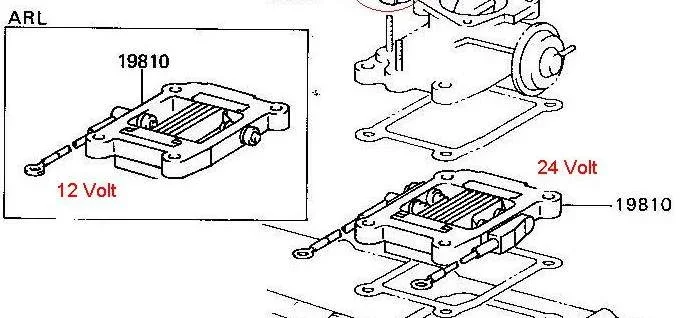
The 12v heater uses a single screen and it is also a smaller screen.

This is how i imagined it works...
 
Has anyone compared the wiring diagram to a 13BT diagram since they both use a screen and are 24V system.
I still can't get my head around how 24V is being reduced to 12V for each side of the screen what would be the purpose why would it not just use the full 24V like a 24V GP system.

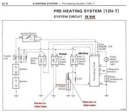
After figuring out where the confusion is in the Toyota way of making a diagram for both 12V and 24V systems in one diagram and showed them in post #17, I did the same for the 13B and BT in this picture. I removed the 12V set up out of this diagram so it's now a 24V only diagram, and (almost) equal to the 12HT diagram.
glow screen 24Volt.JPG

Does this help?

Rudi

glow screen 24Volt.JPG
 
Back to the 12HT and the 24V version, so we (collectively) reckon we could have this as the likely real wiring:

12HTpreheat24Voltquestion.JPG
(I just removed a bit more surplus stuff on top of what you had already removed Rudi.)

But this still doesn't explain that wierd bakelite-type bridge between the two intake terminals as shown here:

CCintakeHeater.jpg

I think Lasse has a good point in that there could be a diode within that.

Or do you think this INSULATOR is just made like that so that it gets supplied as one part rather than two separate parts?

And if the above wiring diagram is correct, PREHEAT (where you want high-wattage/fast-heating) uses only a small proportion of the intake heater element length whereas AFTERGLOW (where you have less need for heat) uses all the element length.

BTW - I know that connecting 24V half way through the element (rather than at its farthest end from the ground) is "overvoltaging" that section and thereby making it glow faster and hotter..... but it still seems odd to me to use just part of the element for preheat and then use the entire element for afterglow..

What do you think about these things Rudi?

Oh and here's another pic thrown in of a 24V version already connected up:
HJ-61 027.jpg

12HTpreheat24Voltquestion.JPG


CCintakeHeater.jpg


HJ-61 027.jpg
 
Last edited:
1. The insulator.
I think it's just what it is. An insulator. Could also be 2 separate insulators but for some reason Toyota made it a double insulator or in other words 2 connected insulators. I think it's just the design. I don't know how to describe it different.
And NO, I don't think that there is a diode inside (see below).

2. The double intake heater element.
When in the pre glow situation the current goes through the #1 relay and through the lower heater element for 14 seconds. Lets say that element is 24 ohm just for the sake of explanation. 24V / 24ohm = 1Amp = 24V x 1amp = 24 Watts.
Let's assume that the upper element is also 24 ohm.
In the after glow situation the current goes through relay #2 and now through the upper AND the lower element for a time between 0 and max 70 seconds depending on the coolant temperature (water temperature sensor).
Now we have 24V / 48 ohm = 0.5 Amp = 24V x 0.5Amp = 12 Watts.

For reference:
Amauri wrote:
Reading section EM-13 in the 12H-t manual, you can see that the automatic system turns on solenoid #1 for 14-seconds during pre-start heating and up to 70-seconds with solenoid #2 for afterglow once the engine is running.

So at start (pre glow) the bottom element produces a 14 second heat boost and when the engine is running (after glow) both elements produce each 1/4 of their power assuming that both element have the same resistance of course.
Maybe somebody can do an ohm test on the intake heater elements?

What do you think Tom (and the rest of the Mud gang of course)?

Rudi
 
1. The insulator.
I think it's just what it is. An insulator. Could also be 2 separate insulators but for some reason Toyota made it a double insulator or in other words 2 connected insulators. I think it's just the design. I don't know how to describe it different.
And NO, I don't think that there is a diode inside (see below).

2. The double intake heater element.
When in the pre glow situation the current goes through the #1 relay and through the lower heater element for 14 seconds. Lets say that element is 24 ohm just for the sake of explanation. 24V / 24ohm = 1Amp = 24V x 1amp = 24 Watts.
Let's assume that the upper element is also 24 ohm.
In the after glow situation the current goes through relay #2 and now through the upper AND the lower element for a time between 0 and max 70 seconds depending on the coolant temperature (water temperature sensor).
Now we have 24V / 48 ohm = 0.5 Amp = 24V x 0.5Amp = 12 Watts.

For reference:
Amauri wrote:


So at start (pre glow) the bottom element produces a 14 second heat boost and when the engine is running (after glow) both elements produce each 1/4 of their power assuming that both element have the same resistance of course.
Maybe somebody can do an ohm test on the intake heater elements?

What do you think Tom (and the rest of the Mud gang of course)?

Rudi
I wasn't disputing that using only half the element length could produce twice the heating power Rudi...

I was just thinking that it was a little odd to be using only a fraction of the length when you're needing maximum heating output.

But then I suspect there wasn't much logic in my thought anyway...

I'm now revising my thinking to believe AFTERGLOW full-element performance is more important than PREHEAT full-element performance... based on the following reasoning...

There's no air turbulence around the element (because there's no piston-movement) during preheat because you're not even cranking yet.

So the only air movement during preheat is the result of convection currents around the glowing section of the element. And the intake manifold (and connecting air hose) above the intake heater then accumulates "a warm slug of air" to help the engine fire when it enters the cold cylinders during the first few engine revolutions. (So using just a small part of the overall element-length for this job is just as effective as if you were using the lot.)

When you look at it this way, having the entire element in use for afterglow makes more sense because at that time (ie during afterglow) there's more need to heat the air throughout its volume (because it's moving fast) as it passes through the intake throat.

But wouldn't it be nice to see one of these heaters glowing ... first with 24V on the black wire and then with 24V on the red wire ....just to see how much of the overall element-length works during each test.


:cheers:
 
Last edited:
Here is my theory:
One day the H engine was born with a glow screen/intake heater instead of glow plugs. This (first) engine was 12V.

Later on there was the need for a 24V version. No problem, all electrical parts can be made in a 24V version except this glow screen for one or some reason. This screen was designed to fit between other components and there was not enough room to change that design.
IntakeHeaters_crop.jpg

By making this screen a bit thicker and changing the first (lower) element to 24V and adding a second (24V) element the problem was solved. Just re-designing this screen, add a wire, et voila. Mission accomplished. New order for Nippon Denso, no big changes and costs for Toyota.

In my previous theory I assumed that both element have the same ohm value.
But it can also be that the first (lower) element has less ohms than the second (upper) element as in a 30/70 or a 20/80 ratio to reach the desired effect. Who knows? An ohm test can shine a light in this matter.

Just my 0.02 cents.

Rudi

IntakeHeaters_crop.jpg
 
Last edited:
Just to clarify a little. Since I last suggested the insulator might be a diode I have bought myself a HJ61 and have had the opportunity to experiment a little.

The studs that the terminals are tighten down to are a part of the intake manifold/butterfly valve construction and derby are grounded. So this insulator are a simple plastic insulators to avoid grounding the terminals. I measured a 0.1v potential between the studs and battery ground but that I blame poor grounding of the intake manifold for :)

The mathematics of BJ40green is correct. Connecting just one yield a higher amperage drain and higher power draw. Connecting both in series will result in lesser amperage draw and lesser power.

If you are in a really cold climate and struggle with cold start you can modify the circuit so that you connect both in parallel for super glow and one for afterglow.
Then you will have 4x more heating power on superglow than what you had on afterglow before or respectively twice the heating power in superglow and afterglow compared to oem design. Just account for higher amperage draw and that wires and solenoid are designed for these loads.

Could modify the original schematic for the high power glow system if thats makes it easier to see :)

Regards
 
My system is not heating at all on my hj61, not even in temps way below 0. After reading all of this, I'm inspired to wire this system directly to the battery with a momentary switch in between so that it always off until I need it. Im thinking hook the black wire up to one direction of the switch for preheat and the red wire on the other switch terminal for afterglow. I would have a 40 amp fuse in between the black wire and the switch, and another between the red wire and the switch, maybe another between the battery and the switch. does any one see any problems with this design? Am I about to blow something up? My plan is to only light the black wire for like 3 seconds, but then after starting, light the red wire for about 15 seconds to reduce white smoke
 
That's what Ive started to do, but not quite sure how to measure the amps. I was thinking run a switch to one selanoid to the preglow wire and a second selanoid to the afterglow wire. Since I don't have any idea how many amps this is taking, not quite sure what kind of selanoid to use.
 

i cant remember the amperage draw on the glow screen, but i would measure the actual draw and wire it up with a solenoid.

That's what Ive started to do, but not quite sure how to measure the amps. I was thinking run a switch to one selanoid to the preglow wire and a second selanoid to the afterglow wire. Since I don't have any idea how many amps this is taking, not quite sure what kind of selanoid to use.

First: Relay and solenoid are the same.
Second: Cut the wires from pin 1 to Preheat relay and pin 5 to After Glow relay.
Hook those wire up to a momentary switch like they use for windows up/down and you're ready!

Rudi
 
Hi guys!
I love this thread its really full of valuable information.
My question is about a 2H to 12HT conversion in a HJ47 pickup. The 12HT is 24V. If I would go with the manual (toggle switch) pre heating version what is the solution about the 24V pre heater unit? Does that needs to be changed to 12V or it's enough if the relays are 12V?
Although I've never tried it myself, some say they've ran the factory 24v glow system on 12 volts after swapping into an fj60/62 and it worked absolutely fine.
 
Although I've never tried it myself, some say they've ran the factory 24v glow system on 12 volts after swapping into an fj60/62 and it worked absolutely fine.
Yes I've heard the same .. some say to glow some extra time with the 24V pre heater and others say to put a transformer before the pre heater only and run the 24V unit.
I definitely won't like to change them to a 12V unit.. maybe if I decide to globe trotter with my 40 and I get to some cold place the 12V is just a joke only for our home climate in Aus.
 
So I’ve had a 12HT in my 60 for a bit. Living in Texas I did not figure I’d need the glow screen. Spent 2 weeks in CO and WY last summer and the truck was a bit disturbed on the sub 35 degree starts. Was in the back of my mind to rig up the system but quite frankly had zero understanding of how it worked. Consulted a bit with a buddy @ceylonfj40nut and then stumbled across this thread and believe I figured out for myself how to do this. I’m actually getting a HJ60 going for a friend @LowDown that had a 12HT transplanted. Truck still has the hj60 harness so I went with one relay and tied it to the red side which I believe gives it an immediate kick. Wired in a momentary switch so it can be held as Long as needed and two...it won’t accidentally be left on. Used the 60 harness and clipped the ground and positive wires that lead into the relay (not the heavy gauge wires bolted to the posts). Then extended the ground to the fire wall and the positive to the dash where it plugs into the momentary switch. The other side of the switch is direct to the battery. This is a 24v system so I looped the switch to the negative terminal on the RHS battery (12v). Relay still fires and sends the voltage to the glow screen. I tested it this way since my personal truck is 12v. Wanted to see if the relay actually works and it does. Question for y’all...do I leave it on the negative post or move it to the positive/24v post? Thanks. Jim
 
Also off topic but at what temp do you guys find you need the glow screen in order to start? Like at what temperature does it become impossible with the heater?

Cheers
 
My HJ60 with a 12HT will start okay down to 3-4deg C (37-40F) without a glow... it is a bit bumpy for a bit but clears up within 5-10 seconds. My normal/typical starting procedure is push the glow button for a few seconds when it goes down to 5-6deg C and hold it for a several seconds after it fires up. It will smoke for a bit but clears up in a minute or so when it's that cold.
It's always starts even at -15 to -20deg C (0deg F) but I have to glow it a bit lunger and pull the hand throttle a couple notches.
 
Thanks for that reply, just I am looking at removing the glow plug/heater...

I live in Australia so generally temps are pretty good but occasionally we see 0 degrees.

Also if I take it to the snow might see temps as low as -4... is it even possible to start at that temp without a heater? (Eg lots of cranking?).

Cheers
 

Users who are viewing this thread

Back
Top Bottom