Voltage Regulator (int.) / How it works (1 Viewer)

This site may earn a commission from merchant affiliate
links, including eBay, Amazon, Skimlinks, and others.

bj40green

Tssss, tssss
Joined
Dec 13, 2010
Threads
32
Messages
3,457
Location
Atenas, Costa Rica
This new thread is about Alternators with Internal Voltage Regulators and is the follow up on my other thread about External Voltage Regulators: -► Voltage Regulator (ext.) / How it works

If you’ve read my other thread you can skip this chapter and go to the 2nd posting.
If you came directly to this thread, read this chapter on the history of the VR for better understanding how it works.

In the beginning (60’s and 70’s) there was the 3 wire Voltage Regulator.
IGN: Voltage from the Ignition witch to the VR. This wire is used to activate the VR and at the same time to “sense” the voltage in the truck commanding the Alternator to FULL, HALF or NO charge via the F (Field) wire to the Alternator.
The 3rd wire is E (Earth) aka Ground. This E wire runs from the VR housing to the Alternator housing and acts as a parallel ground wire to the normal ground circuit. The purpose is to eliminate ground problems in the regular ground circuit.

From ’79 and later the 6 wire VR became available. The only difference with a 3 wire is that this VR is capable of turning an indicator light on or off. Aka “idiot light.” The main reason for this is that a light attracts more attention in case of a charge problem than the Ammeter.
The same 3 basic wires IGN, F and E are used but now there are 3 extra wires. N, L and B.
N (Null) comes from the Alternator and should be “high” when the alternator is spinning.
This N wire activates the Voltage relay, which activates the Regulating relay.
No voltage on the N wire means no “regulating” which results in a warning light that comes “on” on the dashboard. This is done by the L (Lamp) wire.
The warning light (Lamp) is hooked up on one side to 12V. The other side to the L wire on the VR. When the N output is “high”, the L output is also “high” which results in a light bulb that is hooked up on both sides to 12V. In other words; the lamp/light is “off”.
When the N output is Null (0V), the L output is also Null which results in a light bulb that is hooked up between 12V and Null (ground). In other words; the lamp/light is “on”.= NO CHARGE.
To get this circuit working it needs another voltage and that is added trough the B wire.

All good and well but it’s still a mechanical VR with all his little problems.
The disadvantages of a mechanical VR are; moving parts, contacts burning in, contacts stuck together and these VR’s created a noise/interference that the AM radios didn’t like. For that reason a capacitor was added to the VR.


Rudi
 
Last edited:
In the early 80’s IC’s (Integrated Circuits) became available. With these IC’s it became possible to make a VR small enough to fit, at first, on and later inside an Alternator.
These electronic regulators are also known as “Solid State” which means; no moving parts.
The advantages are that there are no longer moving parts and more important that the charge process is now smoothly regulated. Instead of the 3 step regulating (full, half and no charge with the mechanical regulators) the process is now done on a gliding scale.

External VR versus internal VR.
external _ internal VR.JPG

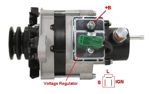
Example of a 3 wire Alternator with S, L and IGN and vacuum pump attached to the back.
Alt int VR 3 wire.JPG

This new generation alternators needed only 3 wires to function (4 if you include the +B terminal).
The VR is now inside (or on top) of the Alternator which reduced the wiring to 3 wires: IGN, L and S.
S = To “sense” the voltage in the system and regulates the charging process.
L = Output high/low to turn the “no charge” light on or off.
IGN = Voltage from the ignition key switch to activate the alternator (on/off).

Time didn’t stood still and the next generation needed only 2 wires to function.
Note that the S terminal is no longer there.

Example of a 2 Wire Alternator with IGN and L. The VR is now inside the Alternator housing.
IMAGE_006_001.jpg

Example of a 2 Wire Alternator with IGN and L. The VR is on top of the Alternator housing
2wire_alternator_text.jpg

Wiring diagram for a 2 wire Alternator
2wire_alternator_wiring_diagram_.JPG

Note that this Alternator has 2 +B terminals.

Rudi
external _ internal VR.JPG
Alt int VR 3 wire.JPG
IMAGE_006_001.jpg
2wire_alternator_text.jpg
2wire_alternator_wiring_diagram_.JPG
 
Last edited:
The same alternator with a capacitor (aka condenser) mounted between the 2nd +B terminal and ground.
20130916_214829_text.jpg

Rudi
20130916_214829_text.jpg
 
Last edited:
3 Wire Alternator with VR on top and pigtail connector.
Alt int VR 3 wire.JPG

The VR when you take it out.
VR int.jpg

2 Wire Alternator with VR on top and cover removed.
20130919_172652.jpg

VR removed.
P1020129.jpg

Rudi
Alt int VR 3 wire.JPG
VR int.jpg
P1020129.jpg
20130919_172652.jpg
 
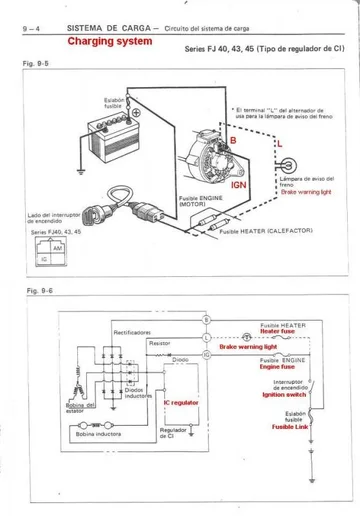
Wiring diagram for a 2 wire Alternator. The L (Lamp) is optional in this diagram.
This diagram is from the 2F engine FSM which I have only in Spanish so I added some translation in red.
VR IC int 2F engine EN_ES.jpg

Rudi
VR IC int 2F engine EN_ES.jpg
 
Wiring diagram for a 3 wire Alternator.
This is a BASIC diagram of how it works.
3 wire alternator basic wiring diagram.JPG

Pay special attention to the S wire when you do a swap or upgrade to an Alternator with a Sense wire.

!!! Don't hook this up to the +B terminal !!!

Toyota_Alt_S_Wire.jpg

Rudi
3 wire alternator basic wiring diagram.JPG
Toyota_Alt_S_Wire.jpg
 
Hi Rudi, great guide, very detailed, but I was wondering if you could give me some advice on my alternator?

I've just converted my 22R Bundera to a 5L diesel and everything seems to have worked perfectly except the alternator :(

Initially I hooked it up as you show above, with lamp at the top, then signal and ignition on the two lower pins (side by side). This seemed to work, with the battery light coming on correctly and the battery charging. I took it for a test drive and it was all good, but then I noticed the next day it wasn't charging the battery any more. I don't know if maybe I shorted it while working in the engine bay (on wiring etc) or something, but it wouldn't make any more than 10.5 volts. I changed the brushes, and had a fiddle around, but no luck, so I got a second alternator off a friend to try out.

This one has different markings on the alternator and different coloured wires on the lead (green, black, blue rather than pink, white and blue that was on the original alternator) but my mate said it should work fine.
Now to rule out any issues with my wiring loom I installed the new alternator and connected the two 'side by side' pins, which I believe to be signal and ignition, to the positive of the battery. Then I started the engine and measured the voltage. It moved from 12 up to 13, 14, 15... and then I turned the engine off cause I didn't want to break a second alternator.....

Now I am very confused as to what to do. I thought I had a reasonable understanding of this, but I feel like I'm just guessing at this point.

Here is a pic of the original alternator:
OriginalAlt.jpg


This is the new one (sorry I forgot to to a pic with it out of the car:
NewAlt.jpg


NewAlt2.jpg

I do notice there is a big number 7 on the original and a number 2 on the new one. What does this mean?

Sorry to hijack your thread, you just seemed so knowledgeable on the subject and I wasn't sure where else to post.

Thanks for your time,
Michael

OriginalAlt2.jpg
 
Argh, I decided to undo to the top of the alternator where I expected the regulator to be and noticed that there doesn't seem to be one in there... I guess that explains why it didn't appear to be regulating... :bang:

I'll have to find an external regulator to suit, and hook that up (hopefully my mate has one still attached to whatever he removed this alternator from). Or is it viable to try replacing the internal regulator in the original alternator?
 
Good, you found the problem yourself :clap: I like that. You've two different alternators.
27030-54243 is with an external (6 wire) VR. What you did is.... you put battery voltage on the F terminal. This F terminal gets a 12V or lower from the regulator. In this case there was nothing to regulate so the voltage went up and up and up and....

27030-54151 is with an internal VR. The VR is on top in that box. Check the VR for loose screws and corroded contacts.
BTW; S stands for Sense. This terminal is sensing the battery voltage and regulates the charging process.

Rudi
 
Thanks for the reply Rudi.

When I replaced the brushes the regulator looked OK, but I'll take it out tonight and have a look to see if there is any noticeable corrosion etc.

I've managed to find an external regulator to suit the second alternator, so I'll have a go at wiring that up on the weekend when it's light out (we are in the middle of winter here, so its dark when I leave for work, and dark when I get home... :(). I really need a bigger shed that can fit my cruiser inside.
 
Hey Rudi,

So I ended up snagging this regulator:
Regulator.jpg


Does this wiring look ok? Sorry for all the noob questions, I just want to make sure I get it right seeing as I managed to kill the first Alternator...

Initially I thought the yellow would be the lamp wire, but the ignition on the alternator plug is the thickest so I figured that would lead to the beefiest wire aside from constant 12?

Thanks for your help,
Mick
 
Sorry, but your diagram is not going to work.
The confusion is in the 3 spade connector. There are several models, they look the same but they are not.
Model 1. E,F,IGN
Model 2. E,F,N
Model 3, L,S,IGN
You're assuming that it has a S terminal. If That's the case it has an internal VR.
So it's not model 3,
We have to figure out what alternator you have there. Please post pics of the part number label, the connector and tell me the colors of the connector wires.

The VR you have there is from a '80 - '90 HiLux or 4Runner

Rudi
 
Yes sorry I reverted back to the internally regulated terminology
5h3ejEPds9e6i6eL2vAM86UEizVhaTMUq3aRddylRzvBFExPnaL7JwM08d0E22ECuKLkY_IjvR6Yq3P5ctwppIIsnNqZjt_PWPte7asAdKKIrll5fto=s0-d-e1-ft


The alternator is the second one I showed above: the 27030-54243.

From memory the connector wires on the Alt are blue, black and green (same orientation as the plug side) but I'll double check tonight when I get home.
 
Here we go, you have nice stuff from a Hi Lux, 4Runner or Dyna. Doesn't matter, this should work.
hook up.JPG

B (Battery) goes to the battery and is basically the same as the S (Sense) terminal on later alternators with an internal VR.
N (Null) is the status of the alternator and activates the L (Lamp) function.
F (Field) is the "regulating" wire to the alternator. This wire is 0V (battery full - no charging), 7V (battery almost full - trickle charge) or 12V (charging).
L (Lamp) the other side of the lamp is connected to +12V.
E (Earth) also known as "ground". Both are already grounded by their housing. This wire is to equalize any potential differences.
IGN (Ignition) is switched 12V from the key switch.

Good luck,

Rudi
 
Last edited:
Thanks for the very clear response Rudi. Excellent diagram.

Now correct me if I'm wrong, but apart from the terrible use of naming in my pic, haven't I wired it up the same as in your pic?

If you re-label my wires you get:
Alternator Plug
E: Black Wire
F: Green Wire
N: Blue Wire

Wiring Loom
B: White Wire (constant 12V from the battery)
L: Yellow Wire (to one side of the lamp circuit)
IG: Red Wire (to the switched 12V i.e. ignition)

As I mentioned in my comment, I wasn't sure which way around the L and IG went. Turns out I was right the first time. That's what I get for over thinking it...

The other thing I was going to ask is how much current do you reckon the B wire would draw out of curiousity? Actually for that matter, how do I know how much current my alternator will put out at maximum?

Thanks,
Mick
 
Hi Mick,

haven't I wired it up the same as in your pic?
Maybe. I didn't have much to work with, especially you labeling the alternator connector wrong. Anyway......

Which B wire are you talking about? The one from the VR draws close to nothing.
The big +B to the battery can deliver some 55Amps, that's how the alternator is rated. If you want to know exactly you'll have to install an Amp meter.

Rudi
 
I was just wondering why the one from the VR was so thick (I mean it's not massive, just larger than I would have thought).

Cool I was thinking around that range, but I wasn't sure where to find the information from. Where did you find that out? Do you have datasheets of some kind?

Thanks for answering my million questions :)

Mick
 

Users who are viewing this thread

Back
Top Bottom