It's pretty much common knowledge that as our 60s & 62s age, the contacts in the mechanical voltage regulator for the fuel & temp gauges can begin to stick and cause the needles to spike, or in bad cases max out and damage the armature that controls the needles from too much current.
I've been working on a permanent fix for this that eliminates the mechanical regulator from the circuit and replaces it with a bolt-in solid state regulator. I figured this thread would be cool for the "gee whiz" of watching the development stages that'll lead up to a final product that I plan on selling through the Marketplace (Storefront, specifically). Funding is very tight so I've got a Kickstarter submitted for approval that (if successful) will fund the remainder of development, equipment I'll need for assembly/testing and an initial production run once I have a PCB design finalized. But since that's not even set in stone yet, here's a bit of an overview up to where I'm at now.
First step was to figure out what I was working with exactly. Our gauges operate by accepting a source voltage that passes through the gauge, through the wire harness, through the sender (which in its most basic form is just a variable resistor) and then to ground. I got out the FSM and scrawled up a rough schematic of the circuit for the fuel and temp gauges based on the resistance values specified.
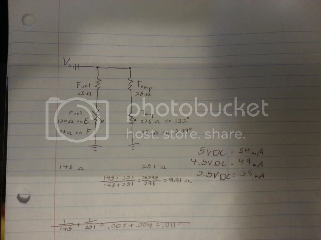
When I take the input voltage(s) and the maximum values of sender resistance I can use Ohm's Law to determine exactly how much current will be pulled from the regulator so that I can ensure I build one that will support it with a little bit of headroom. Unfortunately I've discovered that the values for gauge and sender resistance are far different from what is specified in the FSM. The gauges are described to be about 50Ω. When testing the gauges with my multimeter, both the fuel and the temp gauges read exactly 25Ω resistance, same thing when I used one of the better DMMs at school too. I asked another Mudder to test his gauges and he got the same results, so that verified that there was nothing wrong with my gauges.
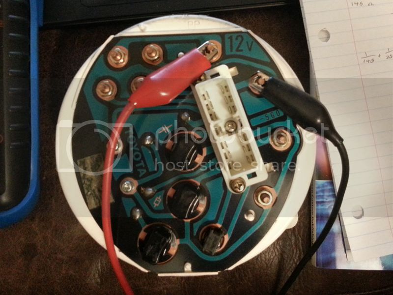
Checking the temp gauge
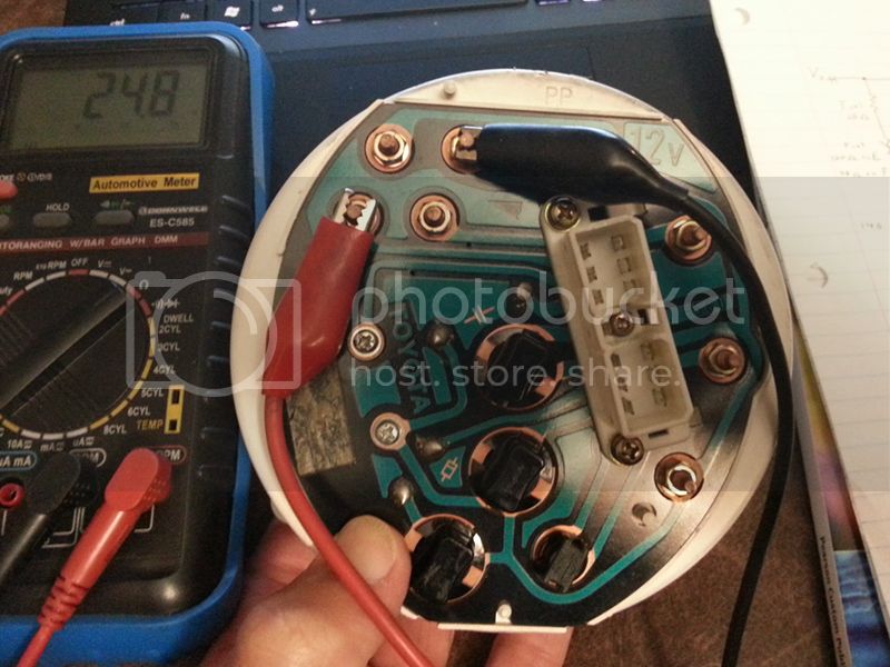
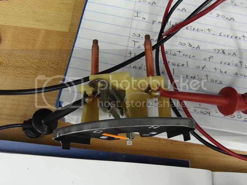
Testing the fuel gauge. You can see my MM reading 24.8 in the pic. It would rapidly bounce between 24.8Ω and 25.0Ω, but using the school's DMM (much more accurate) I was able to take finer readings and got 4,995mΩ, so easily close enough to round to 25Ω.
EDIT: This picture is wrong. I put the leads back on just for the sake of getting a pic. The red lead should've been connected to the post immediately above where it is now, and the black should've been on the post immediately below where it's currently connected. My multimeter is showing the value from when I first read the gauge and hit the hold button.
Now had I been smart I would have assumed that the same would be the case for the senders and ohmed out the ground leads for both gauges one of the several times I've already had the dash apart. Next time I tear into it I'll be doing that with a cold engine and an empty fuel tank so that I can record the maximum resistance of both senders and build a better test bed.
Next was to get a ballpark idea of what input voltage these gauges required, so they got connected directly to the DC power supply and I was able to slowly increase the voltage until the needles read at their upper limit. You can see by the indicators on the PS in the background that with no resistance other than the gauges themselves, 5.0V was the magic number for each.
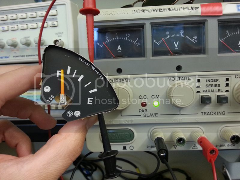
This is to show the workings of our gauges. As current passes through the thin wire, it heats up and bends the armature, which causes the needle to move. No current = "cold" armature = bottomed out gauge.
Next step was to figure out how accurate they would be with a 5V feed and resistances to match what was specified in the FSM. So I threw together a basic test rig to mimic the circuit for the linear voltage regulator that I was going to use for my first regulator.
Current came from the power supply at 14VDC, through the voltage regulator, through the gauges, back through a couple trimmer pots I put in place to simulate the resistance from the senders and back to the negative lead from the power supply. What you see on the DMM is the current measurement between the regulator and the gauges at 297mA. I was going for a simulation of the complete circuit. One thing I noticed while testing was that the regulator got HOT HOT HOT, reaching the point of thermal shutdown. I needed to make sure there would be a heatsink in place if I stuck with linear regulators.
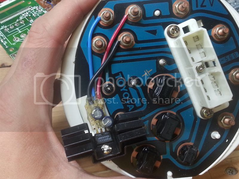
Save for the discrepancy between the FSM's measurement and my actual measurement, everything else seemed kosher. The gauge needles settled in the appropriate spots for the corresponding settings on the pots. Using a small thru-hole breadboard, I soldered a 5VDC linear regulator, three wires and a couple smoothing capacitors into a rough prototype to test in my 62.
Notice the cumbersome heatsink attached to the regulator. Linear regulators are for the most part inefficient in that they will continue to draw a certain amount of current (depending on the output voltage and maximum output current), but any unused current is dispelled as heat. A simpler way to figure it is that the greater the difference between input and output voltages, the more heat a linear regulator will generate. The benefit is that their output voltage is much more stable than that of a switching regulator, which can make them desirable for sensitive electronics (depending on the application). Not being sure just how sensitive the armatures of the gauges are without the inductor in place (black capacitor-looking part inside the fuel gauge), I opted to err on the safe side as a "just in case" measure.
So that I would know that the fuel gauge needle will max out with the correct source voltage, I made sure my tank was topped off. I buttoned my dash back together, started the truck, and the fuel gauge needle only rose just slightly over halfway. After driving my truck and getting the engine good and warm, the temp gauge showed just about half of what it normally does.
So, design 1 was a bust. The heatsink also generated another problem in that it was very easy to snag and accidentally yank when reaching behind the instrument panel. When pulling the panel to remove it, I snagged a section of wiring harness on it and with very little force broke the regulator off of the main assembly. At least the solder joints weren't what broke, so I guess that was a plus I also had a feeling that even with that heatsink in place, the heat some of our trucks see in warm climates would prevent it from conducting enough heat away from the regulator.
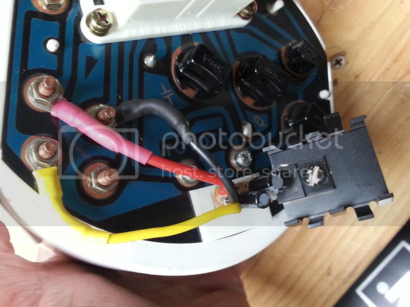
Prototype 2 used a 6.3VDC regulator (still linear), but the same essential design. I also used a dual heatsink setup on this that allowed for less than half the total thermal resistance of the previous heatsink, plus did not protrude nearly as far back as the other.
In the heat of summer here, the inside of my dash measured 163*F at the hottest I measured, which is less than 100* difference from the thermal shutdown point of the regulators I was experimenting with. Not a very large window to dissipate much heat from the regulator, and even less when it's operating and putting out its own heat. But surprisingly, it survived without shutting down. By how narrow of a margin though, I'm not sure. You'll also notice that I didn't bother with ring terminals on this one since it is only a prototype. No sense in wasting consumables when you don't have to.
With 6.3V, my needles were almost where they should be. With a topped off tank, my fuel gauge still only read between 3/4 and full though, so I still have some fine tuning to do yet. I'm waiting on a handful of components needed to build prototype 3, then I'll post more updates as I continue with developing this project.
BTW this is my first "from scratch" project planned, tested and built (and hopefully sold) by me since I started my engineering course, so it'll be pretty cool once I end up with a marketable project
I've been working on a permanent fix for this that eliminates the mechanical regulator from the circuit and replaces it with a bolt-in solid state regulator. I figured this thread would be cool for the "gee whiz" of watching the development stages that'll lead up to a final product that I plan on selling through the Marketplace (Storefront, specifically). Funding is very tight so I've got a Kickstarter submitted for approval that (if successful) will fund the remainder of development, equipment I'll need for assembly/testing and an initial production run once I have a PCB design finalized. But since that's not even set in stone yet, here's a bit of an overview up to where I'm at now.
First step was to figure out what I was working with exactly. Our gauges operate by accepting a source voltage that passes through the gauge, through the wire harness, through the sender (which in its most basic form is just a variable resistor) and then to ground. I got out the FSM and scrawled up a rough schematic of the circuit for the fuel and temp gauges based on the resistance values specified.

When I take the input voltage(s) and the maximum values of sender resistance I can use Ohm's Law to determine exactly how much current will be pulled from the regulator so that I can ensure I build one that will support it with a little bit of headroom. Unfortunately I've discovered that the values for gauge and sender resistance are far different from what is specified in the FSM. The gauges are described to be about 50Ω. When testing the gauges with my multimeter, both the fuel and the temp gauges read exactly 25Ω resistance, same thing when I used one of the better DMMs at school too. I asked another Mudder to test his gauges and he got the same results, so that verified that there was nothing wrong with my gauges.

Checking the temp gauge

Testing the fuel gauge. You can see my MM reading 24.8 in the pic. It would rapidly bounce between 24.8Ω and 25.0Ω, but using the school's DMM (much more accurate) I was able to take finer readings and got 4,995mΩ, so easily close enough to round to 25Ω.
EDIT: This picture is wrong. I put the leads back on just for the sake of getting a pic. The red lead should've been connected to the post immediately above where it is now, and the black should've been on the post immediately below where it's currently connected. My multimeter is showing the value from when I first read the gauge and hit the hold button.
Now had I been smart I would have assumed that the same would be the case for the senders and ohmed out the ground leads for both gauges one of the several times I've already had the dash apart. Next time I tear into it I'll be doing that with a cold engine and an empty fuel tank so that I can record the maximum resistance of both senders and build a better test bed.
Next was to get a ballpark idea of what input voltage these gauges required, so they got connected directly to the DC power supply and I was able to slowly increase the voltage until the needles read at their upper limit. You can see by the indicators on the PS in the background that with no resistance other than the gauges themselves, 5.0V was the magic number for each.


This is to show the workings of our gauges. As current passes through the thin wire, it heats up and bends the armature, which causes the needle to move. No current = "cold" armature = bottomed out gauge.
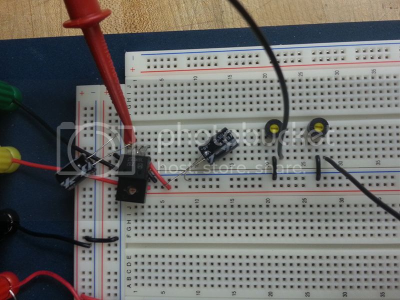
Next step was to figure out how accurate they would be with a 5V feed and resistances to match what was specified in the FSM. So I threw together a basic test rig to mimic the circuit for the linear voltage regulator that I was going to use for my first regulator.


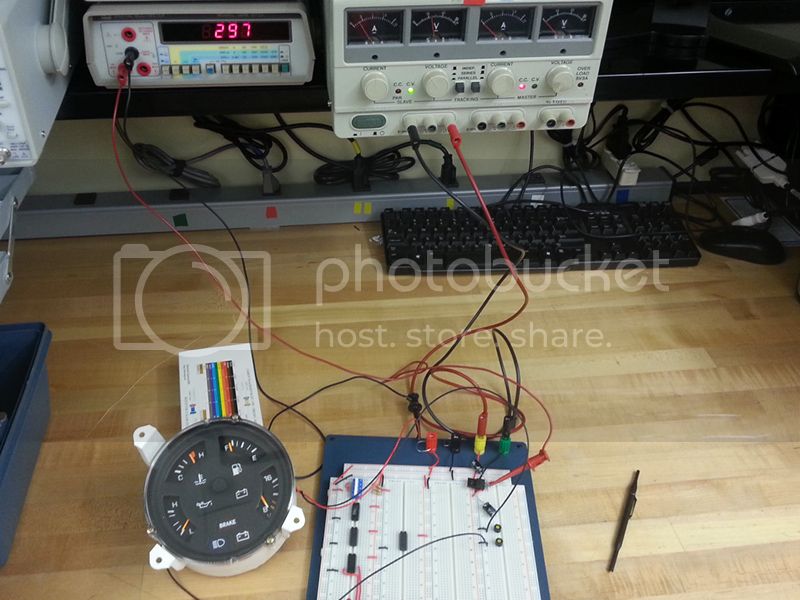
Current came from the power supply at 14VDC, through the voltage regulator, through the gauges, back through a couple trimmer pots I put in place to simulate the resistance from the senders and back to the negative lead from the power supply. What you see on the DMM is the current measurement between the regulator and the gauges at 297mA. I was going for a simulation of the complete circuit. One thing I noticed while testing was that the regulator got HOT HOT HOT, reaching the point of thermal shutdown. I needed to make sure there would be a heatsink in place if I stuck with linear regulators.
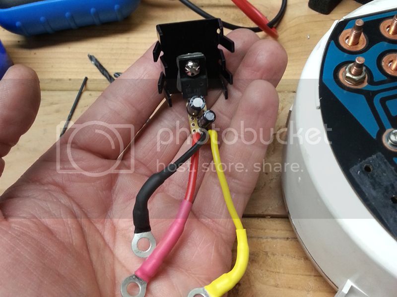
Save for the discrepancy between the FSM's measurement and my actual measurement, everything else seemed kosher. The gauge needles settled in the appropriate spots for the corresponding settings on the pots. Using a small thru-hole breadboard, I soldered a 5VDC linear regulator, three wires and a couple smoothing capacitors into a rough prototype to test in my 62.


Notice the cumbersome heatsink attached to the regulator. Linear regulators are for the most part inefficient in that they will continue to draw a certain amount of current (depending on the output voltage and maximum output current), but any unused current is dispelled as heat. A simpler way to figure it is that the greater the difference between input and output voltages, the more heat a linear regulator will generate. The benefit is that their output voltage is much more stable than that of a switching regulator, which can make them desirable for sensitive electronics (depending on the application). Not being sure just how sensitive the armatures of the gauges are without the inductor in place (black capacitor-looking part inside the fuel gauge), I opted to err on the safe side as a "just in case" measure.
So that I would know that the fuel gauge needle will max out with the correct source voltage, I made sure my tank was topped off. I buttoned my dash back together, started the truck, and the fuel gauge needle only rose just slightly over halfway. After driving my truck and getting the engine good and warm, the temp gauge showed just about half of what it normally does.
So, design 1 was a bust. The heatsink also generated another problem in that it was very easy to snag and accidentally yank when reaching behind the instrument panel. When pulling the panel to remove it, I snagged a section of wiring harness on it and with very little force broke the regulator off of the main assembly. At least the solder joints weren't what broke, so I guess that was a plus
I also had a feeling that even with that heatsink in place, the heat some of our trucks see in warm climates would prevent it from conducting enough heat away from the regulator.Prototype 2 used a 6.3VDC regulator (still linear), but the same essential design. I also used a dual heatsink setup on this that allowed for less than half the total thermal resistance of the previous heatsink, plus did not protrude nearly as far back as the other.

In the heat of summer here, the inside of my dash measured 163*F at the hottest I measured, which is less than 100* difference from the thermal shutdown point of the regulators I was experimenting with. Not a very large window to dissipate much heat from the regulator, and even less when it's operating and putting out its own heat. But surprisingly, it survived without shutting down. By how narrow of a margin though, I'm not sure. You'll also notice that I didn't bother with ring terminals on this one since it is only a prototype. No sense in wasting consumables when you don't have to.
With 6.3V, my needles were almost where they should be. With a topped off tank, my fuel gauge still only read between 3/4 and full though, so I still have some fine tuning to do yet. I'm waiting on a handful of components needed to build prototype 3, then I'll post more updates as I continue with developing this project.
BTW this is my first "from scratch" project planned, tested and built (and hopefully sold) by me since I started my engineering course, so it'll be pretty cool once I end up with a marketable project
Last edited:
