Not starting...fuel issue?

This site may earn a commission from merchant affiliate
links, including eBay, Amazon, Skimlinks, and others.

Battery: Normal- 12.34V Glow position- 11.63V Back to normal- 12.34....

So we have the battery voltage dropping marginally whenever the glow plugs are activated Greg. :hhmm: I didn't expect it to drop as much as 0.71V (12.34 - 11.63) but then again 11.63V is not even 1 volt below the battery's nominal rating of 12V. So I don't think these readings indicate a battery problem. Besides - We know that the glow plugs do draw a high current so they are bound to "stress" the battery a little.

...Glow Relay: Left Connection- 0V- 10.88V- 0V
Center Connection- 12.32V- 10.92V- 12.32V
Right Connection- 0V- 9.53V- 0V........

So these are the G, B and S terminals in this photo (of my glow relay):
relayglow_start.webp

And they are in the circuit as shown here in Amaurer's diagram:

amaurer's.webp

B is the "battery voltage in" to your relay and is your "centre" reading. It reads 10.92V when you're glowing so there has been a further voltage drop of (11.63 - 10.92) = 0.71V along the wire to your relay. But you've still got near-as-dammit 11V available.

G and S should be reading the same value because they are simply the "voltage out" of your glow relay. (We know that S is connected to nothing-at-all within the relay!) And these are your "left" and "right" readings.

So lets take the average of your 10.88 and 9.53 as your "relay voltage out" reading. This is 10.2V. So the relay is feeding just 10.2V to the wiring to your glow controller.

Now I think this is getting a little LOW! You've lost nearly 2V before even getting to your glow controller.

Glow Controller: Left Side- 10.08 Right Side- 9.38....

OK so the glow controller is getting 10.08 volts. (There's bound to be some discrepancies in readings.) And the glow controller is reducing this voltage to 9.38V due to its resistance (and due to its pitiful attempt at "glowing").

...Plugs From firewall to front: 8.89V- 8.89V- 8.83V- 8.78V- 8.78V- 8.75V (Decreasing V may be from repeated trials)...

So the wiring from the glow controller to the glowplug busbar has dropped the voltage further (from 9.38V down to approx 8.8V lets say)

So where does this leave us?

Yes. Clean terminals/connections as Amaurer/Drew suggests and see if you can reduce your voltage drop.

And perhaps we need to take some readings on our glow systems to compare?
relayglow_start.webp
amaurer's.webp
 
Last edited:
I measured my own truck for comparison:

Normal - Glowing
Battery: 12.89 - 12.25
Relay Left: 0 - 10.7
Relay Center: 12.75 - 10.94
Relay Right: 0 - 9.59
Plugs: 0 - 9.0

Battery: almost equal to yours. about .65V between glowing and nonglowing
Relay left: identical
Relay center: again, almost equal
Relay right: equal again
Plugs: right on.

Your system seems to be functioning just fine. Well, it functions just like mine, and I use 10.5V plug, but have never blown one up.

Did you try cleaning the coil in your controller? I couldn't see mine glow for many months until I cleaned the dust off from inside of it.

So do you think I should switch to a 10.5V if these assplode?
Even the brand new right out of the box glow controller didn't light up. I'll clean some things and test the voltage on the new one.

Lost and Amaurer: Let me take this opportunity to thank you both for your concern and advice in this matter. You guys have really been a big help!
 
Thanks for the thanks. But it's a pity we haven't solved anything yet. (Drew and I both like delving into stuff like this anyway.)

As I understand it, you have a 1981 HJ47 (12V battery) with a 2H motor and are using 8.5V plugs in series with a glow controller having part number 28550-47040 . All this appears to be in order. (I don't think you should consider changing to 10.5V plugs like Amaurer is using. I'd be more inclined to say that he should be changing to the same 8.5V plugs that you're running.)

So far, I've been looking at 2 separate problems here:

  • Your glow controller won't glow, and
  • You have become a "glowplug serial killer"
Because you still can't see any glow - even with a brand-new controller, I think your first problem here (glow controller not glowing) must be caused by insufficient current flow. --- which is why we were looking at the possibility of excessive voltage drop occuring.

And my searching (quite extensive now) on MUD shows that most people with this problem found trouble with their connections between their glowplug busbar and their individual glowplugs. (And they solved it by cleaning those terminals/connections to ensure proper electrical contact between the busbar and each and every plug.)

But hang on there :idea::idea:. On the second front (glowplug serial killer) - What if some of your plugs terminals aren't indeed making proper contact with your busbar? This will actually force extra current through those that are. And this could indeed be the cause of those glowplug failures. And, what's more, the lack of overall current flow will indeed also be causing your glow controller to fail to glow!!!!!

So the one problem that could cause both symptoms (no glow in the dash-mounted glowcontroller AND melted plugs) is poor connections between your busbar and your plugs.

So can I suggest you look there again and make doubly sure these connections are all electrically-sound Greg. (And meanwhile - Don't glow your plugs - particularly not for any significant timespan - or else more plugs are likely to become "toast". And if any of your new ones are already "toast" - more will follow (cascade-failure) and your problems will persist of course.)
 
Last edited:
So do you think I should switch to a 10.5V if these assplode?

(I don't think you should consider changing to 10.5V plugs like Amaurer is using. I'd be more inclined to say that he should be changing to the same 8.5V plugs that you're running.)

I agree with Tom, stick with the 8.5V plugs. When I said your system voltages are similar to mine, I was actually noting that, when using 10.5V plugs, my glow is weak, taking 30+ seconds to light the controller. I'm actually convinced that Tom is right on this one; I should be using 8.5V plugs. Its on the todo list... plus, if I blow anything up, I'll just blame him! :D

Tom, would you be so kind as to measure your G and S relay terminal voltage? Greg has 0.6V across his controller (aka across the G and S terminals) and has no glow. I have 1.1V across my controller and have very weak glow (30s+). Since you have nice strong glow it'd be interesting to see what your voltage is; this should be our target.

In any case your controller is not glowing because the voltage across it is too low. The current through the glow system as a whole is directly proportional to the voltage across the controller, so we can infer that your controller isn't lying; you really do have a weak glow. As Tom said, troubleshooting should concentrate on increasing the system current by making better connections.
  1. Take a measurement from the engine itself, preferably a nice clean spot of bare metal near the base of the glow plugs, to the battery negative terminal WHILE GLOWING. [If you measure anything other than 0V then you have a bad engine ground. Very common, and probably the source of your EDIC trouble too]
  2. Then clean your bus bar and glow plug connections.

EDIT: As I think on this, I strongly suspect bad engine grounds. I read so many posts on here sometimes it takes a while to identify just who is posting what. However I checked: you posted about intermittent starter function, then poor glow, and then a stuck EDIC. The common factor in all of those components is that they ground through the engine. Chek those engine grounds good. This is an extremely common problem.
 
Last edited:
Raining all day today so I won't be working on it :(
Starter was toast on the inside. That problem is fixed. I added bonding straps to the engine last year. I'll re-visit those connections and check the V's from (-) on battery to a bare metal spot on the engine while glowing.
If the busbar was bad, wouldn't the voltage be off on some of the plugs? I'll retest the plugs and make sure I am not touching the busbar at all so I am getting voltage of the plug and not the busbar near the plug.
 
... I should be using 8.5V plugs. Its on the todo list... plus, if I blow anything up, I'll just blame him! :D....

:hhmm: It is always nice to be offering ideas on other people's cruisers because then at least I know I won't be paying the cost if my ideas don't work out Drew :D

....Tom, would you be so kind as to measure your G and S relay terminal voltage? Greg has 0.6V across his controller (aka across the G and S terminals) and has no glow. I have 1.1V across my controller and have very weak glow (30s+). Since you have nice strong glow it'd be interesting to see what your voltage is; this should be our target.........

If I end up divorced - It'll be your fault Drew. (I'm still trying to install that new stove/oven - in between sittin on this computer that is. Mind you - I gib-stopped the wall behind the old oven at 1 am this morning so I'm sort-of making progress there.)


... As I think on this, I strongly suspect bad engine grounds. ...................

Instead - my money is on the cause being - that Greg's electrical connections between his busbar and some plugs are "bad" (even though he's checked them before and they appeared "good").

And I withdraw that earlier suggestion of mine that ether-starts could have been to blame (for disintegrating the plugs). That was just me "clutching at straws". I suspect the only problem with ether-starting is that, if you were to make the mistake of "glowing" first, you could "blow your air cleaner to bits" or "blow your exhaust system to bits" because a glowing glowplug would tend to ignite the ether regardless of whether inlet or exhaust valves were open or closed at the time.
....If the busbar was bad, wouldn't the voltage be off on some of the plugs? .....

Yes. - That is, unless some plugs are already burnt-out (open-circuited)

....I'll retest the plugs and make sure I am not touching the busbar at all so I am getting voltage of the plug and not the busbar near the plug.

Since you now have a voltmeter - You could also test between bare metal on the busbar and the "threaded terminal" on each and every plug while someone is "glowing your plugs". Then - If you record any voltage other than "zero" it will conform a poor connection on that plug. (But first you must KNOW all your new plugs are still "good". I am very worried that, since you've destroyed a number of plugs now - some of the new ones may be already damaged! So before doing this test, can you confirm that each and every plug "has continuity through itself" by using the "ohms setting" of your multimeter with the busbar removed - as described earlier in this thread.)

:cheers:

PS. I've just recently worked out (and my searching on MUD confirms that others here have discovered this before me) - that poor electrical connections from-busbar-to-plug-terminals are a common cause of BOTH "glowplug failure" and "failure of the dash-mounted glow controller/indicator to glow". Not only this, but if the connection between the busbar and one plug is poor (or if one plug burns out) - this stresses the remaining plugs because they "try to carry the current that the unconnected (or burnt-out) plug should be carrying" (in addition to their normal "rated current"). And not only this - But the more plugs that fail (or are poorly connected to the busbar) - then the more the remaining plugs will become "stressed". Thus the failure (or poor-connection of) one plug can and DOES lead to the "cascade failure" of the rest.
 
Last edited:
.......Tom, would you be so kind as to measure your G and S relay terminal voltage? Greg has 0.6V across his controller (aka across the G and S terminals) and has no glow. I have 1.1V across my controller and have very weak glow (30s+). Since you have nice strong glow it'd be interesting to see what your voltage is; this should be our target...........

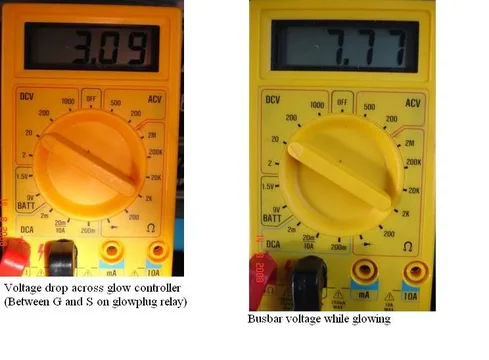
Good idea Drew. I get 3.09 V. Here are some photos (not that they mean any more than words here - But - what the heck:D):

voltageglow1.webp

voltageglow2.webp

Don't ask me how I managed this. - I'm by myself at home at the moment so I did it solo. (Mind you - if my daughter had still been here she would probably have spent all her time in the cruiser "looking at herself in the rear view mirror" or "doing her nails" or other "womanly things". And communication with my wife is somewhat difficult at the best of times. - Instead of turning the key backwards - she'd probably have turned it forwards and run me over! So I was better off doing it solo I'm sure.)

:cheers:
voltageglow1.webp
voltageglow2.webp
 
Wowee 3 volts!! No wonder we have weak glows from the controller!!

Also, with 7.7V at your plugs, no wonder you use 8.5V'ers.

Hm Hm Hm, I need to see what happens with 8.5V plugs.
 
And communication with my wife is somewhat difficult at the best of times. - Instead of turning the key backwards - she'd probably have turned it forwards and run me over! So I was better off doing it solo I'm sure.)

:cheers:

Momentary hijack on;

Reminds me of explaining to my wife that I need her assistance in bleeding the brakes. I'll say, 3 pumps and hold, I crack the bleeder, nothing. This happens a few times and I stand up and say, do that again and I see the throttle linkage moving.

Momentary hijack off.
 
Momentary hijack on;

Reminds me of explaining to my wife that I need her assistance in bleeding the brakes. I'll say, 3 pumps and hold, I crack the bleeder, nothing. This happens a few times and I stand up and say, do that again and I see the throttle linkage moving.

Momentary hijack off.

Our :princess: are obviously "the same breed".
 
Ok. Here is the latest. I pulled all of my new plugs and they all look good No blowouts yet.
Removed my busbar and cleaned all of the connections with wire brush.
To test the continuity of the busbar I put one end on the + battery terminal, and touched each connection point with the grounded voltmeter. Everything was the same voltage as the battery.

I noticed that where the busbar connects to the plugs, each hole was elongated and bent. The cause of this is that the plugs have a small nut holding the plastic insulator in, and a larger flanged washer-nut combo (a nut with a large flat surface on one side). The busbar goes in between these 2 dissimilar surfaces.

To fix this, I took the 6 old flanged nuts and put them on washer-side-up, and the new ones washer-side-down with the busbar sandwiched in between, thinking this would make a better connection and solve all of my problems in life.

I confidently turned the key to glow and anticipated the warm amber illumination flowing forth from the small dark hole.

It didn't.
So I replaced it with the new glow indicator. It also didn't light. Both get wicked hot, but there is no glowing.

Went back to the engine and hooked a battery charger on slow trickle to regulate my battery charge and tested the busbar at each plug, then the plugs themselves. Everything was up at or around 8.9

Tested the engine to - terminal and it read 0.03. It read the same everywhere I did this same test...engine block, bonding strap, frame, body, fender, all read 0.03.

Then I gave up.
 
Ok. Here is the latest. I pulled all of my new plugs and they all look good No blowouts yet.....

If you performed only a visual inspection - Then you really needed to do a "continuity test" on each plug as well (using the "ohms scale of a multimeter" as described earlier). Because I believe a plug can look fine from the outside but still be burnt/open-circuited inside.


...Removed my busbar and cleaned all of the connections with wire brush.
To test the continuity of the busbar I put one end on the + battery terminal, and touched each connection point with the grounded voltmeter. Everything was the same voltage as the battery................

It took me a while to figure this out (I know - I'm slow) - But did you actually "remove the busbar and put one end of it on the +ve battery terminal to test its continuity"? If so- then I think that was a waste of time. A solid conductor like that WILL DEFINITELY HAVE CONTINUITY. But what we really wanted to know was whether it was/is carrying that continuity through TO EACH AND EVERY PLUG by making a "sound/good electrical connection with it".

"Poor connections" will often "reveal themselves" only when they are "under load". Your voltmeter passes "just milli-amps" while those busbar connections are expected to carry currents that are at least a 1000 times higher. So a proper test of them is to have someone glow your plugs while you (with one lead of your voltmeter "earthed") touch the other voltmeter lead on each "plug terminal". In this way, those connections would be under "maximum load". And if one plug is getting much less voltage from the busbar - Then this will show up in this test.

...I noticed that where the busbar connects to the plugs, each hole was elongated and bent. The cause of this is that the plugs have a small nut holding the plastic insulator in, and a larger flanged washer-nut combo (a nut with a large flat surface on one side). The busbar goes in between these 2 dissimilar surfaces.

To fix this, I took the 6 old flanged nuts and put them on washer-side-up, and the new ones washer-side-down with the busbar sandwiched in between, thinking this would make a better connection and solve all of my problems in life..........

Sounds a very good idea to me Greg. A lot of current goes through those plugs. (Enough to drop your batteries output voltage significantly). So a big "electrical-contact-area" is vital. And washers either side of the busbar at each plug terminal should improve the contact area.


....I confidently turned the key to glow and anticipated the warm amber illumination flowing forth from the small dark hole.

It didn't.
So I replaced it with the new glow indicator. It also didn't light. Both get wicked hot, but there is no glowing.

I feel your pain (as they say).


...Went back to the engine and hooked a battery charger on slow trickle to regulate my battery charge and tested the busbar at each plug, then the plugs themselves. Everything was up at or around 8.9 .......

So I take it that this is the voltage test that I was wanting you to do. (As described in the paragraph above that I have highlighted in orange.)

If so, it shows that all busbar connections are indeed fine (IF all plugs have "continuity"). And the only thing I can still think of that could cause your dash indicator/controller to "fail to glow" is that one or more plugs are open-circuited. (Assuming you simply visually checked them and didn't run a continuity/ohms check on them as well.)


...Tested the engine to - terminal and it read 0.03. It read the same everywhere I did this same test...engine block, bonding strap, frame, body, fender, all read 0.03.

Then I gave up.

So you have just 0.03V drop in your earthing (testing to the battery's negative terminal) while you are "glowing your plugs". --- Nothing wrong there (as far as I know).

All I can think of is what I've mentioned above - That is - Do the plug-check properly (assuming you didn't before).

Anybody with any other ideas? (Amaurer/Drew?) I've pretty-well exhausted all I can say (or think of) here.

:cheers:
 
Last edited:
So I set it to Ohms, remove the busbar and touch 1 probe to where the busbar connects and one to a ground. Should I use the negative terminal on the battery or just a random metal place near the plug? To I need to turn the key to the glow position?
What am I looking for? Can this be done with the busbar attached?
 
So you have just 0.03V drop in your earthing (testing to the battery's negative terminal) while you are "glowing your plugs". --- Nothing wrong there (as far as I know).

All I can think of is what I've mentioned above - That is - Do the plug-check properly (assuming you didn't before).

Anybody with any other ideas? (Amaurer/Drew?) I've pretty-well exhausted all I can say (or think of) here.

:cheers:

0.03 is fine.

I don't wanna throw my hands up on ya man, but at this point everything seems to be working fine. I don't know why your controllers don't light up but at this point I'd just run it and see if those plugs last. Your numbers are right on, I doubt you're gonna blow the plugs.

It might be something subtle and irritating - just babbling now, but maybe fractures in the outer parts of the resistance wire have created a thermally isolated outer shell that hides the glow. :confused::confused:
 
So I set it to Ohms, remove the busbar and touch 1 probe to where the busbar connects and one to a ground.......

Yes. (This is indeed the way to check the "continuity" of each plug Greg.)

.. Should I use the negative terminal on the battery or just a random metal place near the plug? ...

I'd just use nearby metal where you can make "effective electrical contact" (such as the alloy intake manifold). But if your earthing is OK (and we think it is from your tests) - then the battery negative terminal is just as good.

.. To I need to turn the key to the glow position?......
Certainly not! For an "ohms-test/continuity-test" you rely on the little battery inside the multimeter for the "testing voltage". You don't need any other power source! (In fact, another power source can damage your meter when you have it set on "ohms".)

..What am I looking for?....

You're looking for a needle deflection/movement. This will prove "continuity" and confirm "a good plug".

:hhmm: Just thinking - Your meter is digital isn't it? (I prefer an analogue meter for this test - That's one with a needle-and scale.) If your meter is digital - it will give a "low resistance reading" (probably close to "zero") if the plug is OK.

No needle deflection (no needle movement) shows "open-circuit" and a "bad/burnt-out plug". (A digital meter will give a very high ohms reading - like "999999999 ohms" or something like that - I must try it myself tomorrow when I get home.)

...Can this be done with the busbar attached?

Certainly not! With the busbar connected you can't tell which plugs have "continuity" and which don't.

:cheers:
 
OK. I've been busy taking some photos at home of "performing continuity/ohms tests on glowplugs".

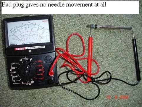
Firstly here is using a cheap analogue meter:

analoguegood.webp

analoguebad.webp

Note: I "cheated" and pretended the glowplug was bad. One of those probes is not actually touching the glowplug metal.

And here using a cheap digital meter:

Here is a "good plug" with the 2 megaohms setting (2000,000 ohms):

2Mohmsgood.webp

It is reading "zero ohms" (0.000 megohms actually)
analoguegood.webp
analoguebad.webp
2Mohmsgood.webp
 
Last edited:
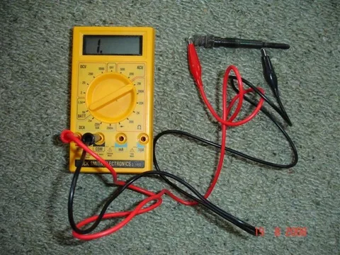
And here is a "bad plug" using the 2Mohm setting again: (Again I "cheated" - The plug is really "good" so to make it look "bad" I made sure one probe wasn't touching.)

2Mohmsbad.webp

The meter is trying to say "a very very very very high value" but because it is "digital cr#p" is just says 1.0 (I thought it would say 9999999999!)

And here is a "good old plug" using the 200 ohms setting. (My meter reckons the plug has a resistance of 1.2 ohms):

200ohmsgood.webp

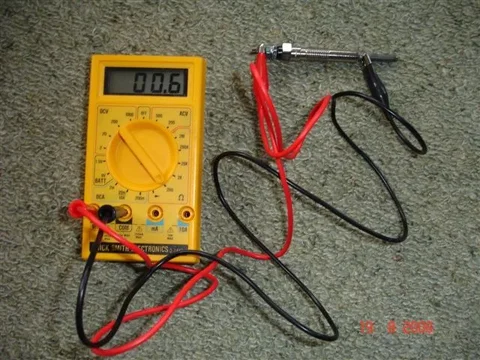
And here is a brandnew plug on the same 200 ohms setting. (My meter reckons this plug has a resistance of 0.6 ohms):

200ohmsnewgood.webp

(Note. All these plugs are 8.5V plugs - as per your vehicle's specs Greg)
2Mohmsbad.webp
200ohmsgood.webp
200ohmsnewgood.webp
 
Last edited:
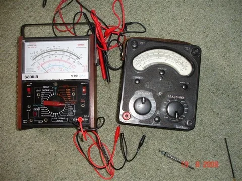
And just to finish off ------- and assuming you want to see the meters that "real men" use ........................ or should I say .............what "we elderly folk" used to use when we were young-uns..........................Here ya go:

REALmeters.webp
REALmeters.webp
 

Users who are viewing this thread

Back
Top Bottom