I have gas......but how much?

This site may earn a commission from merchant affiliate
links, including eBay, Amazon, Skimlinks, and others.

Nicely done my friend. :) Now that I'm going to have a rear bumper w/tire carrier I've considered this setup myself. Alas I must choose between beening yelled at by the wife for spending to much time and money on the cruiser or a secondarly gas tank. Anyways your setup is really sweet, I'll remember this when or if I ever get to my setup.
 
Last edited:
Nice Job Dan!

Just remember, he bought his new and has had 12 years to mod his vehicle. You know what happens to us when we haven't done a mod in a while, we look for one. When Dan runs out of wheeling mods, he will install a capucciono (sp?) machine. That is of course after the beer fridge and tap.
 
Romer said:
Nice Job Dan!

That is of course after the beer fridge and tap.


Fawker.....:rolleyes: U peeked, didn't you?........:mad:


Found an old Hotpoint and I was fixin' to REWIRE IT.....:mad: But, oh no, U had to tip my hand.....:mad:


Just wait til U need something......;)
 
Very nice Dan
Did you get an oem sender or did it come from somewere else.
I am happy this worked out for you, I'm still waiting for the ship to dock.
Steven
 
I off-line orderd a new one from Japan. It came with the gasket and attaching screws.
 
Did you get your transfer pump with your tank? Did you off line a pump? Or source one localy?
 
The pump is a facet/Purolator that I had kicking around the garage. It is a 30GPH transfer/carbureted engine pulse diaphragm type pump. The price was perfect and it works just fine. It ia a bit noisy but since it only operates for a short period of time it does not bother me.
 
Hey Dan
I was rereading the print out of this thread for bed time reading this morning.
I noticed some parts I was hoping you would elaborate on.

{A conroller (I used George's).}
{A project box to put the controller in.}

Me too, sourced through Slee

Could you tell me more about your project box ?

I was thinking I may be able to put the ECU in a film canister with a little bubble wrap to keep it from shaking around? My ECU is not encased in epoxy ! Will I have heat problems or some other kind of problems, is there a better way ?

{to tap into the unused radio circuit for power and illumination.}

Oh can you please tell me which color wires and what they do ? That is a Great place to get power and lights, And I just free'd up the original curcuit when I put in the new stereo.

Well I hope your day goes real well !

Steven
 
The project box came from Radio Shack. They sell these little black boxes of various sizes to put yer geeky projects in and they have a cover that you can screw on. I cut a hole in one end to insert the 9 pin Molex connector that I also got at the rat-shack. I took a couple pics of the box before I stuck it in the vehicle. I will post them from home later.

Switched hot comes from pin 3 in the 10 pin radio plug. Ground is pin 7 and illumination hot is pin 10. Illumination ground comes from pin 5 in the 6 pin radio plug. In my case I moved pin 5 from the six pin plug into pin 8 of the 10 pin plug which was vacant. That way I only had to tie into one connector.


D-
 
All I need is pin 4 and I got a bingo
 
Everybody here has way to much time on their hands, and way to understanding wives. :D

Me included. :D

Junk definately not included. :flipoff2:
 
reffug said:
Everybody here has way to much time on their hands, and way to understanding wives. :D

Me included. :D

Junk definately not included. :flipoff2:

My Wife and I resemble that comment :flipoff2:

And Dan , If I ever run across you in my travels I am deffinently buying you a few #6's :flipoff2:

Steven
 
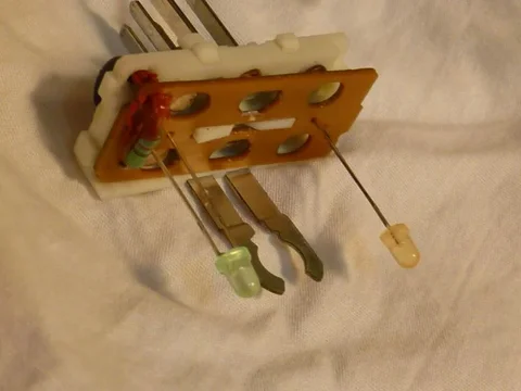
Here are photos and a diagram for wiring a heater switch to function as a selector between sub tank and main tank sending unit signals.

The resistor wire in the top right corner of the PCB is desoldered, the now-vacant hole drilled out to remove the layer of copper surrounding the hole and avoid crossing circuits, a matching hole drilled in the white plastic, and a wire soldered between the resistor and the lower right male terminal, which will be wired to the variable dimmer ground.


P1020101.jpg

P1020102.jpg

P1020103.jpg
P1020101.jpg
P1020102.jpg
P1020103.jpg
 

Users who are viewing this thread

Back
Top Bottom